Category: Manuals

arizona’s drivers manual

Arizona Driver’s License Manual⁚ A Comprehensive Guide

This essential manual, available online and at MVD offices, covers Arizona driving laws, road rules, and safe driving practices. It’s crucial for permit and license tests, ensuring you’re well-prepared for Arizona roads. The manual includes practice questions and answers. The latest version is available on azdot.gov/mvd.

Obtaining the Manual

The Arizona Driver License Manual is readily accessible through multiple convenient avenues. For those who prefer the digital format, the Arizona Department of Transportation (ADOT) Motor Vehicle Division (MVD) website, azdot.gov/mvd, hosts a downloadable PDF version of the manual. This allows for easy access and immediate study from any device with an internet connection. Alternatively, a physical copy can be obtained at any MVD office conveniently located throughout Arizona. This option provides a tangible resource for those who prefer to study offline. The manual is regularly updated to reflect current laws and regulations, ensuring the information remains accurate and relevant. To confirm you have the most current version, always check the ADOT website for the latest edition.

Key Sections of the Manual⁚ Road Rules and Signs

A significant portion of the Arizona Driver License Manual is dedicated to explaining the state’s road rules and the meanings of various traffic signs. This section provides a comprehensive overview of right-of-way laws, speed limits, lane usage, and other crucial driving regulations. Detailed explanations and illustrations are provided for different types of traffic signs, including regulatory signs (speed limits, stop signs), warning signs (curves, intersections), and guide signs (route markers, destinations). Understanding these rules and signs is paramount for safe driving and passing the written driving exam. The manual emphasizes the importance of obeying all traffic laws to ensure the safety of oneself and other road users. It also highlights the consequences of traffic violations, including fines and potential license suspension. Thorough comprehension of this section is vital for prospective drivers in Arizona.

Safe Driving Practices and Techniques

The Arizona Driver’s License Manual devotes a substantial section to safe driving practices and techniques, going beyond simply knowing the rules of the road. This section emphasizes defensive driving, urging drivers to anticipate potential hazards and react accordingly. It covers crucial techniques such as maintaining a safe following distance, properly using turn signals, and understanding the importance of scanning the road ahead and checking mirrors frequently. The manual also highlights the dangers of distracted driving, including the use of cell phones, and provides advice on how to avoid distractions. Safe merging and lane changing techniques are clearly explained, along with strategies for navigating various driving conditions, such as rain, snow, or nighttime driving. Specific instructions are given on how to handle different types of road hazards, such as construction zones or animals crossing the road. Furthermore, the importance of vehicle maintenance and regular inspections is stressed, ensuring that the vehicle is in optimal condition for safe operation.

Arizona Traffic Laws and Regulations

The Arizona Driver License Manual provides a comprehensive overview of the state’s traffic laws and regulations. This section details speed limits, right-of-way rules, and the proper procedures for making turns, lane changes, and passing other vehicles. Specific regulations regarding intersections, stop signs, and traffic signals are clearly outlined, including the penalties for violating these laws. Information on parking regulations, including restrictions on where and how long you can park, is also included. The manual also covers rules concerning the use of headlights, seat belts, and child safety seats, emphasizing the importance of these safety measures. Details on Arizona’s DUI laws are presented, covering blood alcohol content limits and the penalties for driving under the influence. Furthermore, the section covers regulations pertaining to commercial vehicles and other specialized vehicles. Finally, information on reporting accidents and dealing with law enforcement officers during traffic stops is provided to ensure compliance with state regulations and safe interactions with authorities.

Understanding Traffic Signals and Markings

The Arizona Driver License Manual dedicates a section to explaining traffic signals and markings, crucial for safe driving. It thoroughly details the meanings of various traffic lights—red, yellow, and green—and their implications for drivers. The manual also explains the significance of flashing lights, both red and yellow, and how drivers should react in those situations. Furthermore, it clarifies the use of arrow signals, indicating permitted and prohibited turns. Beyond signals, the manual covers different types of road markings, including lane lines, center lines, and shoulder markings. It explains the distinctions between solid and dashed lines, highlighting their implications for passing and lane changes. The guide also clarifies the meaning of various pavement markings, such as crosswalks, stop lines, and yield lines, explaining how drivers should behave approaching these areas. Additionally, the section addresses the meaning and importance of traffic signs, including regulatory, warning, and guide signs, and how drivers should interpret and respond to them. Understanding this information is essential for passing the Arizona driving test and for safe driving in the state.

Preparing for the Written Exam

The Arizona Driver License Manual is your primary resource for acing the written exam; Thorough study is key; the exam directly tests your knowledge of the information within. Familiarize yourself with all sections, focusing on road rules, signs, and traffic laws. Practice tests, available online and in study guides, are invaluable tools. These replicate the actual exam format and difficulty, allowing you to identify weak areas and improve your understanding. Repeated practice strengthens your recall of crucial information. The manual emphasizes achieving an 80% or higher score for passing. Time management is also important during the test. Don’t rush, but ensure you allocate enough time to each question. Understanding the material, not just memorizing, is essential for long-term retention and safe driving. Multiple study sessions, spaced over time, will aid in knowledge retention. Remember, the goal isn’t just to pass, but to become a safe and informed driver.

The Driving Test⁚ Procedures and Requirements

The Arizona driver’s test evaluates your driving skills and knowledge, ensuring you can operate a vehicle safely. Before the test, ensure your vehicle meets specific requirements⁚ operational brakes, speedometer, turn signals, seatbelts, doors, windows, mirrors, horn, and an unobstructed windshield. The examiner will assess your ability to perform various maneuvers, including three-point turns, parallel parking, and safe lane changes. Following traffic laws and demonstrating safe driving habits are crucial. Observe all signals, maintain a safe following distance, and check mirrors frequently. The test also evaluates your ability to handle different road conditions and situations. Smooth, controlled movements and clear communication with the examiner are essential. Remember, your vehicle must be roadworthy and properly insured. The Arizona Driver License Manual provides a detailed description of the test procedures and expectations. Familiarizing yourself with these is crucial for success. A successful driving test signifies your readiness to navigate Arizona’s roads responsibly.

Commercial Driver’s License (CDL) Information

The Arizona Commercial Driver’s License (CDL) manual provides comprehensive information for obtaining and maintaining a CDL. This separate manual details the specific requirements for different CDL classes, endorsements, and medical certifications. Aspiring CDL holders must pass both written and driving tests, demonstrating proficiency in operating commercial vehicles. The written exam covers federal and state regulations, safe driving practices specific to commercial vehicles, and knowledge of vehicle inspections. The driving test evaluates skills such as pre-trip inspections, basic maneuvers, and safe operation in various conditions. Applicants must meet specific medical standards set by the Federal Motor Carrier Safety Administration (FMCSA). The manual outlines the necessary documentation, including medical certificates and driving records. It also addresses important topics like hours of service regulations and hazardous materials endorsements. Arizona’s MVD website (azdot.gov/mvd) offers the complete CDL manual and further resources. Thorough study of this manual is essential for CDL applicants to successfully complete the licensing process.

Vehicle Inspection Requirements

Arizona’s driver’s manual emphasizes regular vehicle maintenance and safety inspections. Before any driving test, ensure your vehicle is in top condition, with operational brakes, speedometer, turn signals, seatbelts, doors, windows, mirrors, horn, and an unobstructed windshield. These are fundamental safety features checked during the driving exam. The manual doesn’t specify the frequency of personal vehicle inspections, but emphasizes the driver’s responsibility to maintain a safe vehicle. For commercial vehicles, the requirements are significantly more stringent, detailed in the separate CDL manual. These inspections involve a thorough check of various components, ensuring the vehicle’s roadworthiness and compliance with safety regulations. Failure to maintain a vehicle in safe operating condition may result in citations and penalties. Understanding the importance of vehicle inspections is key to safe driving and passing the driving test. Regular maintenance and attention to vehicle condition are crucial for both personal and commercial drivers in Arizona.

Resources for Further Learning

Beyond the Arizona Driver License Manual, numerous resources exist to enhance your driving knowledge and skills. Online practice tests, available through various websites and apps, offer opportunities to familiarize yourself with the exam format and content. These platforms often provide feedback and explanations, reinforcing your understanding of traffic laws and regulations. Many driving schools throughout Arizona offer comprehensive courses, covering both theoretical knowledge and practical driving skills. These courses can provide personalized instruction and address individual learning needs, helping to build confidence and competence behind the wheel. Additionally, the Arizona Department of Transportation (ADOT) website offers further information and resources, including contact details for inquiries and clarifications. Utilizing these supplementary resources can significantly improve your preparedness for the driver’s license exam and contribute to safer driving habits in the long term; Remember, continuous learning is essential for responsible and safe driving practices on Arizona roads.

Contact Information and Additional Support

For questions or clarifications regarding the Arizona Driver’s License Manual or the licensing process, several avenues for support are available. The Arizona Department of Transportation Motor Vehicle Division (ADOT MVD) provides phone numbers for assistance⁚ Phoenix at 602-255-0072, Tucson at 520-629-9808, and a toll-free number for other Arizona locations at 1-800-251-5866. For individuals with hearing or speech impairments, a TDD service is accessible at 602-712-3222. These contact numbers offer direct access to knowledgeable representatives who can address your specific inquiries and provide guidance. Additionally, the ADOT MVD website (azdot.gov/mvd) serves as a comprehensive online resource, providing access to FAQs, downloadable forms, and other pertinent information. Exploring the website’s resources can often resolve questions quickly and efficiently. Remember, seeking assistance when needed is crucial; don’t hesitate to utilize these contact options for a smoother and more informed experience navigating the Arizona driver’s licensing process.

oster convection oven user manual

Oster Convection Oven User Manual⁚ A Comprehensive Guide

This manual provides comprehensive instructions for your Oster convection oven. It covers safety, setup, features, cooking modes, cleaning, troubleshooting, parts, customer service, FAQs, and warranty information. Find answers to your questions and ensure optimal oven performance.

I. Introduction to Your Oster Convection Oven

Congratulations on your new Oster convection oven! This versatile appliance offers a range of cooking options, from baking and roasting to air frying and grilling. Designed for convenience and efficiency, your Oster oven simplifies meal preparation. This manual will guide you through its features and functions, ensuring you get the most out of your purchase. We’ll cover everything from unpacking and setup to advanced cooking techniques and maintenance. Whether you’re a seasoned chef or a novice cook, this user-friendly guide will empower you to create delicious meals with ease. Familiarize yourself with the safety precautions before starting. Understanding the oven’s controls and various cooking modes is crucial for achieving optimal results. Explore the different settings and discover the possibilities of this powerful kitchen tool. Prepare to elevate your culinary experiences with your new Oster convection oven. Remember to always consult the manual for specific instructions and safety guidelines.

II. Safety Precautions and Important Information

Before operating your Oster convection oven, carefully review these safety precautions⁚ Always unplug the oven from the power outlet before cleaning or performing any maintenance. Never immerse the oven in water or other liquids. Ensure adequate ventilation around the oven to prevent overheating. Use oven mitts or potholders when handling hot surfaces or removing food. Never leave the oven unattended while in operation, especially when using high heat settings. Keep children and pets away from the hot oven and cords. Do not touch the heating elements while the oven is on. Place the oven on a stable, heat-resistant surface. Avoid placing flammable materials near the oven. Inspect the power cord regularly for any damage and replace if necessary. If the oven malfunctions, immediately unplug it and contact Oster customer service. Do not attempt to repair the oven yourself. Always refer to the specific instructions provided in this manual for your model. Following these safety guidelines will ensure safe and efficient use of your Oster convection oven.

III. Getting Started⁚ Unpacking and Setup

Carefully unpack your Oster convection oven from its shipping box. Inspect the oven for any signs of damage during transit. If any damage is found, immediately contact the retailer or Oster customer service. Remove all packing materials, including plastic bags and styrofoam. Locate all included accessories, such as baking pans, racks, and the user manual. Ensure that the oven is placed on a stable, level, and heat-resistant surface. The surface should be large enough to accommodate the oven and provide sufficient clearance around it for ventilation. Avoid placing the oven on a flammable surface or near any flammable materials. Before plugging in the oven, ensure that the electrical outlet is properly grounded and can handle the oven’s power requirements. Check the voltage rating on the oven and ensure it matches your home’s electrical supply. Once the oven is positioned and ready, plug it into the outlet. Familiarize yourself with the control panel and functions before operating the oven. Refer to Section IV for details on oven features and controls. Now you’re ready to start using your new Oster convection oven!

IV. Understanding Oven Features and Controls

Your Oster convection oven boasts a range of features designed for ease of use and optimal cooking results. The control panel typically includes a digital display showing the selected temperature and cooking time. You’ll find various function buttons or dials for selecting cooking modes like bake, broil, convection bake, toast, and potentially others depending on your model. A temperature dial or buttons allow you to precisely set the oven temperature within a specified range (usually between 150°F and 450°F). A timer lets you set the cooking duration. Many models incorporate a convenient keep-warm function to maintain food temperature after cooking. Some Oster ovens also feature additional functionalities such as air frying or grilling. The oven’s interior includes adjustable racks for versatile cooking arrangements. A removable crumb tray simplifies cleaning. Consult the specific diagram in your user manual for a detailed layout of your model’s control panel and interior components. Understanding these features and their operation will allow you to efficiently and safely prepare a wide variety of dishes.

V. Preheating Your Oster Convection Oven

Preheating your Oster convection oven is crucial for achieving optimal cooking results, ensuring even browning and faster cooking times. Before placing food inside, allow sufficient time for the oven to reach the desired temperature. The necessary preheating time may vary depending on your oven model and the selected temperature. Generally, a preheating period of 5 to 7 minutes is recommended for most recipes. However, always check your specific oven’s manual for precise instructions. To preheat, simply select the desired cooking mode (usually “Bake” or “Convection Bake”) and set the temperature using the control panel. Ensure the oven is empty except for the baking pan or rack if required by the recipe. The oven will typically indicate when it has reached the set temperature, either through an audible signal or visual cue on the digital display. Once the preheating is complete, carefully place your food in the oven and begin cooking according to your recipe’s instructions. Proper preheating is essential for ensuring consistent and delicious results with your Oster convection oven.

VI. Cooking Modes and Functions

Your Oster convection oven boasts a variety of cooking modes designed to enhance your culinary experience. These modes offer versatility for various dishes, ensuring optimal results every time. “Bake” is ideal for cakes, casseroles, and other baked goods, utilizing even heat distribution for consistent cooking. The “Broil” setting provides intense top heat, perfect for searing meats or adding a crispy crust to your dishes. “Toast” is self-explanatory, offering adjustable settings for different bread types and browning preferences. The “Convection Bake” function utilizes a built-in fan to circulate hot air, leading to faster and more even cooking than traditional baking methods. This is particularly advantageous for larger items like roasts or pizzas. Many models offer additional settings such as “Pizza,” “Keep Warm,” or specific air fry functions. Understanding these modes is essential for achieving desired outcomes. Always consult your specific oven’s manual for detailed instructions on each function and its optimal use. Selecting the right mode ensures your dishes are cooked perfectly, showcasing the capabilities of your Oster convection oven.

VII. Using the Convection Setting for Even Cooking

The convection setting on your Oster oven utilizes a powerful fan to circulate hot air, ensuring even heat distribution throughout the cooking chamber. This results in faster cooking times and more uniformly cooked food compared to traditional baking. For optimal results when using the convection setting, preheat your oven for 5-7 minutes before placing your food inside. This allows the fan to thoroughly heat the air, leading to more even browning and cooking. Properly spacing food items on the baking sheet is crucial; avoid overcrowding to ensure good air circulation. Convection baking is especially effective for large items like roasts or casseroles, ensuring the entire dish cooks evenly without hotspots. When using convection, you may need to slightly adjust cooking times and temperatures compared to traditional baking recipes. Consult your oven’s manual for specific recommendations or refer to convection-specific recipes. Experiment to discover the ideal settings for your favorite dishes. Remember, the key to successful convection cooking is proper preheating and strategic food placement to maximize the fan’s efficiency.

VIII. Cleaning and Maintenance of Your Oven

Regular cleaning is essential to maintain your Oster convection oven’s performance and longevity. Always unplug the oven and allow it to cool completely before attempting any cleaning. For routine cleaning, wipe the exterior with a damp cloth and mild detergent. Avoid using abrasive cleaners or scouring pads that could scratch the surface. The interior requires more attention. Remove the crumb tray and wash it with warm, soapy water. For stubborn spills or baked-on food, consider using a commercial oven cleaner, following the manufacturer’s instructions carefully. Apply the cleaner, let it sit for the recommended time, and then wipe clean with a damp cloth. Never immerse the oven itself in water. Pay attention to the heating elements; avoid direct contact with cleaning solutions to prevent damage. The oven door’s exterior can be cleaned with a glass cleaner for a streak-free shine. After cleaning, ensure all parts are completely dry before plugging the oven back in. Regular cleaning prevents grease buildup and ensures even heat distribution for optimal cooking performance. Periodically check the oven’s interior for any loose or damaged parts. Consult the troubleshooting section if you encounter any issues.

IX. Troubleshooting Common Issues

This section addresses common problems encountered with Oster convection ovens. If your oven isn’t heating properly, check the power cord and outlet to ensure a secure connection. Verify that the oven is correctly plugged in and the circuit breaker hasn’t tripped. Inspect the heating elements for any visible damage or buildup. If the oven is heating unevenly, ensure proper rack placement and avoid overcrowding the oven. Food cooked too quickly on the outside and slowly on the inside might indicate incorrect temperature settings or improper preheating. Refer to the cooking guides for recommended temperatures and times. If the oven is making unusual noises, check for any loose parts or obstructions within the oven cavity. A malfunctioning fan could indicate a need for professional repair. If the controls aren’t responding correctly, check for any foreign objects or spilled liquids interfering with the control panel. Consult the diagram in this manual if needed to locate the parts you need to check. Ensure the oven has cooled completely before attempting any troubleshooting. If problems persist after checking these points, please refer to the warranty information or contact Oster customer service for assistance.

X. Where to Find Replacement Parts

Finding replacement parts for your Oster convection oven is straightforward. First, identify the specific part you need. The model number, typically found on a sticker on the oven itself, will be crucial in locating the correct component. You can then explore several avenues to find your part. Oster’s official website often has a parts section where you can search by model number. This is a reliable source for genuine Oster parts. Alternatively, many online retailers specializing in appliance parts carry a wide selection of Oster components. Search these sites using your model number for the best results. Local appliance repair shops are another excellent option. They may stock common parts or be able to order them for you. Always verify the part’s compatibility with your specific Oster oven model before purchasing. Finally, consider contacting Oster customer service directly if you’re having trouble locating the part you need. They can provide guidance or direct you to authorized retailers. Remember to keep your proof of purchase handy when ordering parts to assist with warranty claims if necessary.

XI. Contacting Oster Customer Service

Should you encounter any issues with your Oster convection oven, or require assistance beyond the scope of this manual, contacting Oster Customer Service is recommended. Their dedicated team is prepared to address various inquiries, from troubleshooting technical problems to clarifying operational procedures. Before reaching out, gather essential information, such as your oven’s model number and the nature of the problem. This will expedite the resolution process. You can typically find contact information, including phone numbers and email addresses, on the Oster website’s customer support page. Look for a dedicated “Contact Us” or “Support” section. Their website may also offer FAQs or troubleshooting guides that could quickly resolve your query. If you prefer a phone call, note that wait times may vary depending on the time of day and call volume. Be prepared to describe your situation clearly and concisely. For complex technical issues, having your model number readily available will significantly help the customer service representative diagnose and address the problem efficiently. Consider keeping a record of your interaction with customer service, including dates, times, and the names of representatives, for future reference.

XII. Frequently Asked Questions (FAQs)

This section addresses common queries regarding your Oster convection oven. Many users wonder about preheating; the manual recommends preheating for optimal results, typically 5-7 minutes, depending on the desired temperature and the specific recipe. Questions about cleaning often arise; always unplug and allow the oven to cool completely before cleaning. Use a damp cloth for the exterior and a mild detergent for removable parts. Avoid abrasive cleaners. Another frequent question concerns cooking times; these vary greatly based on the food and recipe, so consult your chosen recipe for guidance. Understanding the various cooking modes is crucial; familiarize yourself with the oven’s functions (bake, broil, convection, etc.) to achieve desired outcomes. Some users inquire about troubleshooting; refer to the troubleshooting section of this manual for solutions to common issues. If problems persist, contact Oster customer service. Regarding replacement parts, Oster provides information on their website, often with links to authorized retailers or service centers. Finally, warranty information is usually available on the oven’s packaging, the Oster website, or within this manual itself. Remember to always refer to your oven’s specific model manual for detailed instructions.

XIII. Warranty Information

Your Oster convection oven is protected by a limited warranty. The duration and specifics of this warranty vary depending on your location and the specific model of your oven. To access the full details of your warranty coverage, carefully review the warranty document that came packaged with your appliance. This document typically outlines the length of the warranty period (often one year from the date of purchase), what is covered under the warranty (generally defects in materials and workmanship), and what is not covered (damage from misuse, neglect, or unauthorized repairs); Keep your proof of purchase (such as your receipt) in a safe place; you will need it to make a warranty claim. If you encounter a problem with your oven that appears to be covered under the warranty, contact Oster customer service directly. They can guide you through the warranty claim process, which may involve providing proof of purchase, photos of the defect, and possibly returning the faulty unit for repair or replacement. Remember, unauthorized repairs will likely void your warranty. Be sure to properly follow all the instructions within this manual and the original warranty documents for best results.

ender 3 v3 se manual

Creality Ender-3 V3 SE User Manual⁚ A Comprehensive Guide

This guide provides a complete overview of the Creality Ender-3 V3 SE 3D printer. Learn about setup‚ operation‚ maintenance‚ troubleshooting‚ and firmware updates. Access various resources including online manuals and downloadable PDFs. Explore detailed specifications and features for optimal printing.

Accessing the Ender-3 V3 SE Manual

Locating your Creality Ender-3 V3 SE user manual is straightforward. The primary method is via Creality’s official website. Navigate to their support or download section‚ usually accessible from the homepage. Search for “Ender-3 V3 SE” or the specific model number. You’ll find the manual available as a downloadable PDF file‚ often in multiple languages‚ including English. Ensure you download the latest version for the most up-to-date information and safety guidelines. Alternatively‚ some users report finding a basic manual on an SD card included with the printer; however‚ this may not be comprehensive. Third-party websites may also offer the manual‚ but always verify authenticity and download only from reputable sources to avoid potential malware or outdated instructions. Remember that accessing the official Creality manual guarantees accuracy and ensures you have the most current version‚ crucial for optimal performance and troubleshooting. Should difficulties arise‚ contacting Creality’s support team directly will provide assistance and resolve any access issues promptly.

Downloading the PDF Manual

Downloading the Creality Ender-3 V3 SE PDF manual is a simple process. Begin by visiting Creality’s official website. Locate their support or downloads section; this is usually easily accessible from the homepage. Search for “Ender-3 V3 SE” or your printer’s exact model number to ensure you obtain the correct manual. Once located‚ click on the link to download the PDF file. The file size may vary‚ but it’s generally quite manageable. Before downloading‚ ensure you have sufficient space on your device. After the download completes‚ locate the saved file; it will typically be in your downloads folder or a designated location you selected during the download process. Open the PDF file using a suitable PDF reader application (such as Adobe Acrobat Reader‚ which is free and widely available). The manual should open‚ allowing you to view and print the instructions as needed. Remember to check for the latest version available on Creality’s site. Always download from the official source to ensure you have the most accurate and up-to-date information. Downloading from unofficial sites may lead to outdated or incorrect instructions.

Online Versions and Manuals

Beyond the downloadable PDF‚ Creality often provides online versions of their Ender-3 V3 SE user manual. These online manuals offer several advantages. Firstly‚ they are readily accessible‚ eliminating the need for downloading and storage. Secondly‚ online versions are often updated more frequently than downloadable PDFs‚ ensuring users always have access to the latest information and any revisions or corrections. Creality’s official website is the primary location to find these online manuals; Look for a support or documentation section‚ often linked prominently on the homepage. Navigating to the Ender-3 V3 SE product page should reveal links to online documentation. The online manual may be formatted for easier online reading‚ with features like interactive elements or better search functionality than a standard PDF. Some users may find online manuals easier to navigate‚ particularly when needing to quickly locate specific instructions or troubleshooting steps. However‚ keep in mind that reliable internet access is required to view online manuals. While the official Creality site is the best option‚ third-party sites may also host copies. Always exercise caution when using alternative sources to ensure the credibility and accuracy of the information provided. Checking the source’s reliability is crucial to avoid potential misinformation.

Firmware Updates and Downloads

Regular firmware updates are crucial for optimal performance and to address any bugs or compatibility issues with your Creality Ender-3 V3 SE 3D printer. These updates often include improvements to printing speed‚ accuracy‚ and overall stability. They may also introduce new features or enhance existing functionalities. To download the latest firmware‚ visit Creality’s official website. Navigate to their support or download section‚ usually easily accessible from the homepage. Locate the Ender-3 V3 SE product page‚ which should contain a link to firmware downloads. You’ll likely find different firmware versions listed‚ possibly categorized by date or feature set. Choose the most recent stable release unless you have a specific reason to select an older version. Download the firmware file‚ typically a ZIP archive containing the necessary files. The manual will provide detailed instructions on how to install the new firmware onto your 3D printer. The process usually involves using an SD card to transfer the firmware files to the printer’s control board. Always back up your current firmware before updating. This allows reverting to the previous version if issues arise after the update. Carefully follow Creality’s instructions to avoid damaging your printer during the update process. After installation‚ test your printer to ensure everything is functioning correctly. Regularly check Creality’s website for new firmware releases to keep your Ender-3 V3 SE running smoothly and efficiently.

Troubleshooting Common Issues

This section addresses frequently encountered problems with the Creality Ender-3 V3 SE 3D printer. One common issue is inconsistent layer adhesion‚ often caused by a poorly leveled bed or insufficient bed temperature. Ensure your bed is properly leveled using the printer’s auto-leveling feature or manual adjustments as described in the manual. Check that the bed temperature is appropriate for the filament being used. Insufficient extrusion can result from clogged nozzles or incorrect filament feed settings. Try cleaning the nozzle with a needle or replacing it if necessary. Review the filament feed settings in your slicer software and ensure they are correct for your specific filament type. If prints warp or peel off the bed‚ try using a glue stick‚ hairspray‚ or other adhesion promoters. Make sure your bed is clean and free of debris. Inconsistent print quality can stem from various causes‚ including incorrect nozzle temperature‚ inconsistent filament feeding‚ or vibrations during printing. Check your nozzle temperature‚ ensure proper filament flow‚ and minimize external vibrations. If your X-axis or Y-axis shows unusual movement‚ check the belts for tightness and alignment. Review the manual’s instructions on belt tension and adjustment. Finally‚ consult Creality’s official support resources or online forums for assistance with more complex problems. The online community offers extensive troubleshooting tips and solutions contributed by fellow users. Remember to always consult the user manual for specific instructions and detailed steps for resolving these issues. Safety precautions should be taken when troubleshooting hardware issues.

Assembly and Setup Instructions

The Creality Ender-3 V3 SE 3D printer’s assembly process is generally straightforward‚ though careful attention to detail is crucial. Begin by unpacking all components and verifying their presence against the provided parts list. The assembly typically starts with the frame‚ attaching the various components such as the Z-axis‚ X-axis‚ and Y-axis. Secure all screws and ensure the components are firmly attached. Install the heated bed‚ taking care to connect the wiring correctly. Next‚ attach the extruder assembly‚ including the nozzle and filament feeder. Double-check all wiring connections before proceeding. The installation of the control board and display screen usually follows‚ connecting the various cables according to the labeled ports. The display screen provides a user interface for controlling various print parameters. Once the physical assembly is complete‚ proceed with the initial setup. This involves leveling the print bed to ensure optimal print adhesion. The Ender-3 V3 SE may feature an auto-bed leveling system‚ simplifying this process. However‚ manual leveling might still be required for fine-tuning. Install the appropriate filament‚ usually PLA‚ ensuring it is properly loaded into the extruder. Power on the printer and follow the on-screen instructions to complete the setup and calibration procedures. Familiarize yourself with the printer’s user interface and menu options‚ allowing for easier control and navigation during printing. Consult the user manual for detailed‚ step-by-step instructions with diagrams and images for each step of the assembly and setup process.

Printer Specifications and Features

The Creality Ender-3 V3 SE boasts a range of features designed for reliable and high-quality 3D printing. Key specifications include a sizable build volume‚ allowing for the creation of larger and more complex prints. The printer’s sturdy frame ensures stability during operation‚ minimizing vibrations and enhancing print accuracy. A crucial feature is the inclusion of a removable and flexible magnetic print bed‚ simplifying print removal and improving adhesion. The Ender-3 V3 SE often incorporates a silent motherboard‚ reducing noise levels during printing. This contributes to a quieter and more comfortable printing experience. Material compatibility is another significant aspect‚ with the printer generally supporting a wide variety of filaments‚ including PLA‚ ABS‚ TPU‚ and PETG. This versatility allows for diverse project possibilities and exploration of different material properties. The user-friendly interface‚ often featuring a responsive LCD screen‚ makes operation intuitive for both beginners and experienced users. The printer’s design emphasizes ease of use and accessibility. Precise control over printing parameters‚ including temperature‚ speed‚ and other settings‚ is usually achievable through the user interface or via slicing software. Many models include features like auto-bed leveling‚ which significantly simplifies the setup and calibration process. The Ender-3 V3 SE typically offers a balance of affordability and performance‚ making it a popular choice among hobbyists and professionals alike. Regular firmware updates from Creality often enhance functionality and address any potential issues‚ ensuring optimal performance over time. Detailed specifications‚ including print area dimensions‚ nozzle size‚ and power requirements‚ are typically found in the accompanying user manual.

Operating the Printer⁚ A Step-by-Step Guide

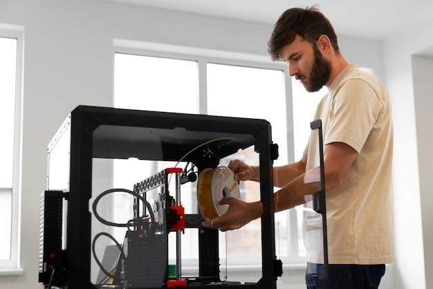
Operating the Creality Ender-3 V3 SE involves several key steps. First‚ ensure the printer is properly assembled and leveled. Prepare your chosen filament‚ ensuring it’s correctly loaded into the extruder. Then‚ use the printer’s control panel or slicing software to select the desired print settings‚ including temperature‚ speed‚ and layer height. These settings are crucial for achieving optimal print quality and depend on the filament type being used. Next‚ prepare your 3D model file using slicing software to generate G-code instructions that the printer understands. The choice of slicing software is flexible and depends on user preference. After the G-code is generated‚ transfer it to the printer via an SD card or through direct connection if supported. Start the printing process using the printer’s controls. The printer will automatically heat up to the specified temperatures and begin extruding filament layer by layer. Monitor the printing process‚ addressing any anomalies that may occur. Common issues might include filament jams‚ layer adhesion problems‚ or nozzle clogs. Consult the troubleshooting section of the manual if such issues arise. Once the printing is complete‚ carefully remove the finished print from the print bed. Allow the print to cool completely before handling to avoid warping or damage. After each print‚ perform basic maintenance‚ such as cleaning the nozzle and print bed. This ensures the longevity and performance of your 3D printer. Regular maintenance is essential for consistent‚ high-quality results.

Maintenance and Care Tips

Regular maintenance is key to ensuring your Creality Ender-3 V3 SE 3D printer delivers consistent‚ high-quality prints. Begin by cleaning the nozzle after each print session. Accumulated residue can affect print quality and lead to clogging. Use a specialized nozzle cleaning tool or a brass brush to remove any filament buildup. The print bed also requires periodic cleaning. Remove any residual filament or debris using a scraper or spatula. Avoid using harsh chemicals or abrasive materials that could damage the print bed surface. Regularly inspect the extruder for signs of wear and tear. Check for loose screws‚ damaged components‚ or filament jams. Tighten any loose screws and replace damaged parts as needed. Lubricate moving parts such as the Z-axis screws and linear rails to reduce friction and ensure smooth operation. Use a high-quality lubricant designed for 3D printers. Keep the printer’s internal components clean and free of dust and debris. Use compressed air to remove dust buildup in hard-to-reach areas. Always unplug the printer from the power source before performing any maintenance tasks. This is a crucial safety precaution to prevent electrical shocks. Store your filament properly in a cool‚ dry place to prevent moisture absorption‚ which can degrade the filament and affect print quality. Use airtight containers with desiccant packets to maintain optimal filament condition. Finally‚ regularly check and update the printer’s firmware to ensure you have access to the latest features‚ bug fixes‚ and performance improvements. Following these maintenance tips will extend the lifespan of your Ender-3 V3 SE and ensure you get the best possible prints every time.

fleetwood rv repair manuals pdf free download

Finding Fleetwood RV Repair Manuals⁚ A Comprehensive Guide

This guide helps locate Fleetwood RV repair manuals. Explore online resources like the official Fleetwood website and third-party databases. Utilize online RV forums for advice and potential manual uploads. Remember to search specifically for appliance manuals if needed, especially for older Fleetwood models. Many manuals are available as free PDF downloads.

Online Resources for Fleetwood RV Manuals

The digital age offers convenient access to Fleetwood RV manuals. Many owners have shared their manuals online, often as PDFs, through various platforms. Websites specializing in RV manuals, like ManualsLib, frequently host user-submitted documents, providing a valuable resource for those seeking specific information. Remember to verify the accuracy and relevance of any downloaded manual before using it for repairs. Always cross-reference information with multiple sources to ensure accuracy, especially for critical maintenance or repair procedures; Some online forums dedicated to RVs and Fleetwood models specifically offer assistance and links to downloadable manuals. Consider searching for your particular model year and model number in conjunction with “manual” or “PDF” to refine your search and increase the likelihood of finding relevant documentation.

Accessing Fleetwood’s Official Website

Fleetwood’s official website is a primary source for owner’s manuals and potentially repair information. While not all manuals may be directly downloadable as PDFs, the site often provides links to authorized dealers or service centers who can supply manuals or offer digital access. Navigation might require specifying your RV’s year, model, and possibly even the Vehicle Identification Number (VIN). Look for sections labeled “Support,” “Owners,” or “Service,” as these often contain links to documentation or contact information. Remember that newer models are more likely to have digital manuals readily available. Older models may require contacting customer service directly or searching alternative online resources. The website may also provide details about warranty information and authorized repair shops, which can be helpful in obtaining assistance even if a specific manual isn’t available for download.

Utilizing Third-Party Manual Databases

Several websites specialize in compiling and offering access to various owner’s and repair manuals, including those for RVs. Sites like ManualsLib are known for their extensive collections. Searching these databases often involves specifying the brand (Fleetwood), model, and year of your RV. While some manuals might be freely available as PDF downloads, others may require a subscription or a one-time purchase. Always verify the legitimacy of the website and the source of the manual before downloading to avoid malware or inaccurate information. Check user reviews and ratings to gauge the reliability of the provided documents. Cross-referencing information found in multiple sources is always recommended to ensure accuracy. Remember to carefully review the terms of service and copyright information before using any downloaded material. These third-party sites can be invaluable resources, but caution and due diligence are essential.

Exploring Online RV Forums and Communities

Engaging with online RV communities can be surprisingly helpful in your quest for Fleetwood RV repair manuals. Websites and forums dedicated to RVs often have sections where owners share information, advice, and resources. Posting a request specifying your Fleetwood RV’s model and year increases your chances of finding someone who possesses the manual you need. Many owners might have digitized versions and are willing to share them. Always be polite and respectful when asking for assistance. You can also search existing forum threads. Someone may have already asked a similar question, and the answers provided might include links to relevant manuals or alternative solutions. Remember to check multiple forums, as the level of activity and helpfulness varies between online communities. These platforms provide a valuable human element in your search and often yield unexpectedly helpful results;

Searching for Specific Appliance Manuals

Your Fleetwood RV likely contains various appliances from different manufacturers (refrigerator, air conditioner, water heater, etc.). Finding repair manuals for these individual components requires a targeted approach. Start by identifying the brand and model number of each appliance; this information is usually found on a label affixed to the appliance itself. Then, use a search engine to search for “[appliance brand] [appliance model] repair manual PDF.” Many manufacturers post their manuals online for free download. Alternatively, check the manufacturer’s official website. Their support section usually includes a library of manuals, often categorized by product line or model number. If you can’t find the manual through these avenues, consider contacting the appliance manufacturer’s customer service directly. They might be able to provide you with a digital copy of the manual or direct you to a reliable resource. Remember, having separate manuals for each appliance simplifies troubleshooting and maintenance.

Locating Manuals for Older Fleetwood Models

Finding manuals for older Fleetwood RVs can be challenging, as digital archives weren’t always standard practice. Begin your search by visiting the official Fleetwood website; while they may not have every manual available online, they might have some older models in a digital archive or provide contact information for support. Explore online forums and communities dedicated to RVs and Fleetwood owners. These platforms often have members who share scanned copies of their manuals or have leads on where to find them. Websites specializing in vintage RV parts or manuals are another good resource; these sites often have a collection of older documents. Consider searching online auction sites or used-book marketplaces. Some sellers might offer manuals as part of their listings, or you could directly request them. Finally, don’t hesitate to contact Fleetwood’s customer service; even if they don’t have a digital copy, they may be able to guide you toward alternative resources or point you to a previous owner who might still have their manual.

Troubleshooting Common Fleetwood RV Issues

Facing Fleetwood RV problems? Start by identifying the issue and gathering information. Consult your owner’s manual’s diagrams and schematics for guidance. Seek advice from experienced RV owners online or in person. If needed, contact Fleetwood customer service or consider professional repair services.

Identifying the Problem and Gathering Information

Effective troubleshooting begins with precise problem identification. Before diving into repairs, thoroughly document the issue. Note the specific system malfunctioning (e.g., refrigerator, plumbing, electrical). Record the exact symptoms⁚ Is there a complete failure, intermittent problem, or unusual noise? Detailed observation is key. Take photos or videos to aid in diagnosis and later communication with repair professionals. Check all fuses and circuit breakers before assuming a more complex problem. Consider when the problem started—was it after a specific event or gradual? This information streamlines the troubleshooting process and helps you find the right solution faster, potentially avoiding unnecessary repair attempts.

Gathering this data efficiently saves time and effort, leading to quicker resolution of the issue. This methodical approach is crucial for both DIY repairs and professional assistance. Write down everything you observe, even seemingly minor details, as they might be critical clues in pinpointing the root cause.

Using Diagrams and Schematics from Manuals

Fleetwood RV repair manuals often include detailed diagrams and schematics invaluable for troubleshooting. These visual aids clarify the system’s layout, component locations, and wiring pathways. Before starting any repair, carefully study the relevant diagrams. Identify the specific component causing the problem. Trace wires and connections to understand their function and relationship to other parts. Schematics are particularly useful for electrical and plumbing systems, showing the flow of electricity or water, identifying potential blockages or short circuits. By understanding the system’s architecture, you can pinpoint the faulty component more accurately. Cross-reference diagrams with your observations of the malfunctioning system. This combined approach allows for a more informed and efficient repair process, minimizing guesswork and potential damage.

Remember to always disconnect power before working on electrical components to prevent injury. Use the diagrams to understand how each part interacts within the larger system, ensuring a safe and successful repair.

Seeking Advice from Experienced RV Owners

When tackling Fleetwood RV repairs, tapping into the collective knowledge of experienced RV owners can prove invaluable. Online forums and communities dedicated to RVs, such as those found on Reddit or dedicated to specific Fleetwood models, are excellent resources. These platforms often host discussions on common Fleetwood issues and their solutions. Describe your problem clearly, including the specific Fleetwood model and year, and any troubleshooting steps you’ve already taken. Include relevant photos or videos to aid in diagnosis. Experienced owners may have encountered similar issues and can offer insights based on their personal experiences. They can share tips, techniques, and even direct you to specific parts suppliers or repair shops. However, always verify any advice received with your manual and use caution before implementing suggestions. Remember that safety should always be your top priority.

While seeking advice is helpful, remember that professional guidance might be necessary for complex repairs.

Contacting Fleetwood Customer Service

If your search for Fleetwood RV repair manuals proves fruitless, or if you require further assistance with repairs, contacting Fleetwood’s customer service department is a viable option. Their contact information, including phone numbers and possibly email addresses, can usually be found on the official Fleetwood website. When contacting them, be prepared to provide specific details about your RV, such as the model year, model number (often found on a sticker inside the RV), and a description of the problem. Having your Fleetwood Identification Number (FIN) readily available will expedite the process. Clearly explain your need for repair manuals or any other technical assistance you require. Note that customer service representatives might not have every manual available, particularly for older models. They may direct you to alternative sources or offer suggestions for finding the information you need. Be polite and persistent in your communication; a positive attitude increases the chances of a successful interaction. Remember to keep a record of all communication with Fleetwood customer service for your records.

Considering Professional RV Repair Services

If your attempts to locate Fleetwood RV repair manuals and independently troubleshoot issues prove unsuccessful, engaging professional RV repair services is a prudent next step. Many RV repair shops possess extensive experience with Fleetwood models and have access to specialized tools and parts. They can accurately diagnose complex problems and execute necessary repairs effectively. Before selecting a service provider, research local options and read online reviews to gauge customer satisfaction. Inquire about their experience with Fleetwood RVs and their diagnostic capabilities. Request a detailed estimate outlining labor and parts costs before authorizing any work. Ensure the shop is properly licensed and insured for your protection. While professional repair isn’t free, it avoids potential costly mistakes from DIY attempts without proper guidance. A qualified technician can often provide valuable insights into future maintenance needs, preventing more serious issues down the line. Remember to obtain all necessary warranties and guarantees for the completed repairs.

Maintaining Your Fleetwood RV

Proactive maintenance is crucial for extending the lifespan of your Fleetwood RV and preventing costly repairs. Regularly consult your owner’s manual for recommended maintenance schedules and procedures specific to your model. This includes tasks like checking tire pressure and tread depth, inspecting fluid levels (engine oil, coolant, transmission fluid), and lubricating moving parts. Cleaning and inspecting the exterior is also vital; this helps prevent rust and water damage. Pay close attention to seals and caulking around windows and doors to prevent leaks. Interior upkeep involves regularly cleaning appliances and checking for any malfunctions. Keep track of your RV’s systems, including plumbing, electrical, and propane. Consider annual professional inspections to identify potential issues before they escalate. Proper storage is essential when not in use; this includes protecting against the elements and pests. These proactive steps contribute to a safer and more enjoyable RVing experience; Remember, preventative maintenance is far more cost-effective than emergency repairs.

rosemount 2120 manual

Rosemount 2120 Manual⁚ A Comprehensive Guide

This manual provides a complete guide for the Rosemount 2120 Level Switch‚ covering installation‚ operation‚ and maintenance. Detailed instructions and safety precautions ensure optimal performance and user safety. Consult this guide for troubleshooting and technical specifications.

Introduction and Overview

The Rosemount 2120 Level Switch‚ a reliable and versatile instrument‚ utilizes vibrating short fork technology for precise liquid level detection. Its suitability extends to a wide range of liquid applications‚ making it a valuable asset across diverse industries. This manual serves as your comprehensive guide to understanding‚ installing‚ operating‚ and maintaining the Rosemount 2120. We will cover key aspects‚ from initial setup and electrical connections to advanced troubleshooting and safety procedures. The Rosemount 2120’s robust design ensures accuracy and longevity even in demanding environments. Its compact size and various mounting options allow for seamless integration into existing systems. Understanding the principles of operation‚ outlined later‚ will enhance your ability to utilize the device effectively and safely. This manual is designed to empower you with the necessary knowledge to maximize the performance and lifespan of your Rosemount 2120 Level Switch. We emphasize safety throughout‚ providing clear warnings and guidelines to prevent accidents and ensure regulatory compliance. With a wide selection of materials and connection types‚ this device is tailored to meet the specific requirements of your application‚ offering flexibility and customization. Proper understanding of the information provided in this manual is crucial for safe and efficient operation.

Installation Procedures and Guidelines

Before commencing installation of the Rosemount 2120 Level Switch‚ ensure you have carefully reviewed all safety precautions detailed in this manual. Failure to adhere to these guidelines could lead to serious injury or equipment damage. The installation process begins with careful consideration of the mounting location. Proper alignment of the vibrating fork is critical for accurate readings. For pipe installations‚ ensure the fork is correctly positioned to avoid interference with the fluid flow. In tank installations‚ consider the potential for obstructions or build-up that might affect the sensor’s performance. Mechanical sealing is crucial to prevent leaks and maintain the integrity of the system. Various sealing options are available depending on the specific application and process fluid. The manual provides detailed diagrams and instructions for each type of connection‚ including threaded‚ flanged‚ and hygienic options. Pay close attention to torque specifications to ensure a secure and leak-proof seal. After mechanical installation‚ proceed to electrical connections‚ ensuring proper grounding and adherence to all wiring diagrams. Remember to always disconnect power before working on any electrical components. Thoroughly test the system after installation to verify proper functionality and calibration. Refer to the troubleshooting section if you encounter any issues during the installation or testing phases. Accurate installation is paramount for the reliable and safe operation of the Rosemount 2120 Level Switch.

Electrical Connections and Wiring Diagrams

Safe and correct electrical connections are crucial for the proper operation of the Rosemount 2120 Level Switch. Before making any connections‚ always ensure the power supply is disconnected. Refer to the provided wiring diagrams specific to your Rosemount 2120 model and configuration. These diagrams illustrate the correct connections for power‚ output signals‚ and any additional features such as relay outputs or load switching. The diagrams clearly show the terminal designations and wire colors for easy identification. Pay close attention to voltage and current ratings to prevent damage to the device. Proper grounding is essential for both safety and noise reduction. Ensure the grounding wire is securely connected to a suitable earth ground point. Use appropriate wire sizes and connectors to ensure reliable electrical connections and avoid overheating. After making all connections‚ carefully inspect them to verify proper seating and secure fastening. Before restoring power‚ visually check the connections one last time. Incorrect wiring can lead to malfunction‚ damage‚ or even hazardous situations. The manual also provides information on various output options‚ including PNP and PLC switching‚ allowing for integration into a wide range of control systems. Always consult the relevant sections of the manual before making any changes to the electrical connections. Following these instructions ensures safe and reliable operation of your Rosemount 2120 Level Switch;

Operational Modes and Settings

The Rosemount 2120 Level Switch offers flexible operational modes and settings to adapt to diverse applications. The device features a selectable mode switch‚ allowing for either “Dry On” or “Wet On” operation. “Dry On” mode activates the output when the sensing fork is not immersed in liquid (detecting a low level)‚ while “Wet On” activates the output when the fork is submerged (detecting a high level). This adaptability is crucial for various applications requiring either high-level or low-level detection. Furthermore‚ the Rosemount 2120 allows for adjustable time delay settings‚ ranging from 0.3 to 30 seconds. This feature minimizes false switching caused by liquid turbulence or splashing‚ ensuring reliable and accurate level detection even in challenging process conditions. Adjusting the time delay is simple‚ usually involving a rotary switch or a similar control on the device itself. Consult the manual’s specific instructions for your model’s precise adjustment procedure. The LED indicator on the device provides visual feedback on the operational status and helps identify any potential issues. Understanding the different operational modes and how to configure the time delay settings is essential for optimizing the Rosemount 2120’s performance in your specific application. Proper configuration ensures accurate level detection and reliable system operation. Always refer to the manual for detailed instructions and settings relevant to your particular Rosemount 2120 model.

Troubleshooting and Maintenance

Regular maintenance and troubleshooting are crucial for ensuring the longevity and accuracy of your Rosemount 2120 Level Switch. The first step in troubleshooting is often a visual inspection. Check the LED indicator for any unusual flashing patterns‚ as these might indicate specific problems; Refer to the manual’s LED indication table to decipher the meaning of different flash rates. If the switch is not functioning correctly‚ verify the electrical connections and ensure power supply integrity. A simple continuity test can often pinpoint a faulty connection. The magnetic test point allows for a quick check of the switch’s operation without needing full system access. This feature enables a convenient and efficient way to verify sensor functionality. Periodically inspect the housing for any signs of physical damage or corrosion‚ especially in harsh environments. Clean the sensor’s exterior as needed to remove any build-up of process fluids or contaminants that could interfere with its operation. Remember‚ the Rosemount 2120 might require specific calibration procedures depending on its configuration and applications. Consult the manual for detailed calibration steps‚ if needed. For more complex issues or situations exceeding your expertise‚ contact Emerson’s technical support or a qualified technician. Replacing electronic cassettes or other components may also be necessary. The manual provides detailed instructions on replacing these parts‚ ensuring that the procedure is done correctly and safely. Preventative maintenance‚ along with proper troubleshooting steps‚ will extend the operational life of your Rosemount 2120 Level Switch and ensure reliable performance for years to come. Always follow safety guidelines when performing any maintenance or troubleshooting activities.

Safety Precautions and Warnings

Before installing‚ operating‚ or maintaining the Rosemount 2120 Level Switch‚ carefully read and understand all safety precautions and warnings outlined in this manual. Failure to follow these guidelines could result in serious injury or death. Only qualified personnel should perform installation‚ maintenance‚ and troubleshooting. Always disconnect the power supply using a properly installed and labeled double-pole‚ single-throw (DPST) switch before undertaking any maintenance or repair procedures. This ensures complete electrical isolation and prevents accidental electric shock. Exercise caution when handling the device‚ as sharp edges or components might exist. Wear appropriate personal protective equipment (PPE)‚ including safety glasses and gloves‚ to mitigate potential hazards associated with the process environment. Pay attention to the surrounding area during installation and operation to avoid potential hazards. Ensure adequate ventilation in confined spaces to prevent the accumulation of potentially hazardous gases. The Rosemount 2120 is designed for specific applications; using it outside of the specified parameters may compromise its functionality and safety. Proper grounding and bonding are essential to prevent electrical hazards. Follow all relevant local and national electrical codes during installation and operation. Consult the appropriate sections of this manual for specific safety guidelines related to each task. If any uncertainty or concern arises during any procedure‚ immediately cease operations and consult a qualified technician or Emerson’s technical support. Always prioritize safety; it is paramount throughout the entire lifecycle of the Rosemount 2120 Level Switch;

Specifications and Technical Data

The Rosemount 2120’s specifications vary depending on the model and options selected. Refer to the specific model data sheet for complete details. However‚ some general specifications include⁚ operating temperature ranges typically spanning from -40°C to +150°C (-40°F to +302°F)‚ though this can vary with specific material selections. Process connections are available in a wide variety of styles‚ including threaded (NPT‚ BSPT‚ BSPP)‚ flanged‚ and hygienic clamp connections. The housing material options include various metals and plastics‚ chosen for their compatibility with the process fluid and environment. Electrical output options include various switching voltages and current ratings‚ along with relay or direct load switching capabilities. The sensing element is a vibrating fork‚ offering reliable performance in diverse liquid applications. The device features a user-selectable time delay to minimize false switching due to turbulence or splashing. Maximum process pressure ratings vary depending on the process connection and housing material. Dimensions and weights will also vary with the specific model and options. The Rosemount 2120 is designed for use in a wide range of applications but is not suitable for all liquids or conditions. Always check the compatibility of the selected model with the specific process parameters before installation. Consult the relevant documentation for detailed specifications and compliance certifications. Emerson’s website and technical support provide additional resources and detailed information for specific model configurations and technical data sheets.

Appendix⁚ Model Codes and Certifications

Rosemount 2120 model codes incorporate specific designations indicating features and certifications. The initial “2120” identifies the product line. Subsequent alphanumeric characters specify process connection type‚ material‚ electrical output‚ and safety certifications. For example‚ codes may include designations for intrinsically safe versions‚ meeting standards such as NAMUR‚ and other safety certifications like ATEX; Consult the current Emerson Rosemount product catalog and data sheets for the most up-to-date model code information. These documents detail the meaning of each character within the model code‚ allowing for accurate identification of specific product features and capabilities. Certifications listed on the model data sheet confirm compliance with various industry standards and regulatory requirements. These certifications are crucial for ensuring the safe and reliable operation of the instrument in different applications and geographical regions. Always verify that the chosen model meets all necessary certifications for the intended installation environment. The documentation will also clarify the specific certifications applicable to each model‚ including those related to explosion-proof operation and hygienic design. The appendix often includes a table cross-referencing model codes with their associated certifications and features. This facilitates selection of the correct model for specific application needs. Contact your Emerson Rosemount representative for assistance in interpreting model codes and selecting the most appropriate instrumentation for your application. Remember to always refer to the most current official documentation for the most accurate and up-to-date information.

peco thermostat manual

Peco Thermostat Manual⁚ A Comprehensive Guide

This manual provides a complete guide to Peco thermostats, covering various models like the T180 and T8000. Learn about programming, troubleshooting, and advanced features. Find answers to common questions and contact information for Peco customer support. Ensure safe and efficient thermostat operation.

Introduction to Peco Thermostats

Peco manufactures a range of thermostats designed for diverse applications, from residential to commercial settings. Their product line includes programmable and non-programmable models catering to various heating and cooling systems. Peco thermostats are known for their user-friendly interfaces, energy-efficient features, and reliable performance. Many models offer advanced functionalities like setback programming, multiple temperature setpoints for different times of day, and compatibility with various HVAC systems. These thermostats aim to provide precise temperature control, contributing to enhanced comfort and energy savings. The Performance PRO series, for example, supports single-stage, multi-stage, and heat pump applications, showcasing their adaptability. Some models offer 7-day, 5/2-day, 5/1/1-day, or 1-day programmable operation, allowing for customized scheduling. The clear digital displays provide easy readability of current and set temperatures, simplifying operation. Peco thermostats integrate seamlessly into existing systems and are designed for simple installation, making them a practical solution for various needs. Whether you need basic temperature control or advanced programmable features, Peco offers a suitable option. Before operating your specific Peco thermostat, always refer to its individual instruction manual for detailed setup and usage information. This ensures optimal performance and avoids potential issues. Consult the manual for specific details on your model and its unique features.

Finding Your Peco Thermostat Manual

Locating your Peco thermostat manual is crucial for understanding its features and ensuring proper operation. First, check the physical packaging your thermostat came in. The manual is often included within the box alongside the thermostat itself. If the original packaging is unavailable, thoroughly examine the thermostat unit. Some models have a small printed label or sticker indicating a model number or website for accessing manuals online. This model number is essential for searching for the correct manual. Then, search online using the model number and “Peco thermostat manual.” Reputable websites like ManualsLib or the official Peco Manufacturing website are excellent resources. Many manufacturers provide downloadable PDF versions of their manuals for easy access. If you encounter difficulties finding your manual online, consider contacting Peco customer support directly. Their contact details are usually found on their official website. They can assist you in locating the correct manual or provide alternative support methods. Remember to always verify the authenticity of any online manual source to ensure you’re using the correct instructions for your particular thermostat model. Using an incorrect manual can lead to confusion and potentially damage your thermostat. Providing the model number to customer support or search engines will help you find the accurate and updated information you need. Careful attention to these steps will help you quickly locate and utilize your Peco thermostat manual, facilitating easy setup and operation.

Peco Thermostat Models⁚ T180, T8000, and Others

Peco offers a range of thermostats designed for diverse applications, from residential to commercial settings. The T180 model, frequently mentioned in online resources, is a programmable thermostat suitable for fan coil systems. Manuals for this model often detail programming options, including setting different temperatures for various times of the day and days of the week. The T8000, described as the “Performance PRO,” is another popular model, indicated by online documentation as catering to both single-stage and multi-stage heating/cooling systems, including heat pumps. Manuals for the T8000 generally cover advanced features and commercial applications. Beyond the T180 and T8000, Peco’s product line likely includes other models with varying functionalities and features. The specific features and capabilities of each model will be detailed in its respective user manual. To ensure you have the correct operating instructions, always refer to the manual corresponding to your precise Peco thermostat model number. This model number is usually prominently displayed on the thermostat itself, and it’s crucial for locating the appropriate manual, whether in print form or as a downloadable PDF. Remember that each model may have unique programming sequences, display indicators, and troubleshooting steps, so consulting the correct manual is essential for successful operation and avoiding potential issues. Accessing the correct manual ensures that you have the most accurate and up-to-date instructions for your specific Peco thermostat.

Understanding Your Thermostat’s Display

The Peco thermostat display is your primary interface for monitoring and controlling your home’s temperature. A liquid crystal display (LCD) with a backlight is common, providing clear visibility. The display usually shows the current ambient temperature of the room, prominently displayed as a larger number. A smaller number often indicates the set temperature – the target temperature you’ve programmed the thermostat to maintain. Depending on the Peco model, you might see additional indicators on the display, such as the current operating mode (heating, cooling, or auto), fan status, and any active programming modes. For instance, “HOLD” might indicate that the thermostat is temporarily overriding its programmed schedule. Some models might use icons to represent modes, while others rely on text abbreviations. Understanding these symbols is crucial for effective operation. Your user manual should provide a comprehensive legend or key explaining each element of the display. This legend is invaluable for deciphering the information presented on the screen and correctly interpreting the thermostat’s status. Refer to your specific Peco thermostat’s manual for a detailed explanation of its display elements, including any specific icons or abbreviations used. Familiarizing yourself with the display’s indicators will greatly enhance your ability to use and maintain your Peco thermostat effectively.

Programming Your Peco Thermostat⁚ A Step-by-Step Guide

Programming your Peco thermostat involves setting desired temperatures for different times of the day and days of the week. Most Peco models offer programmable options, allowing you to customize heating and cooling schedules for energy savings and comfort. The exact steps will vary depending on your specific Peco thermostat model (T180, T8000, etc.), so always refer to your model’s specific instruction manual. Generally, you will use buttons on the thermostat to navigate menus, select days, and input times and temperatures. You’ll typically set up different temperature setpoints for various periods like “Wake,” “Day,” “Evening,” and “Sleep.” Some models allow for 7-day, 5/2-day, or other scheduling options. The process often involves entering the desired temperature for heating and cooling separately for each time period. Remember to save your changes after programming each day’s schedule. Many Peco thermostats offer a “Copy” feature, simplifying the process by allowing you to duplicate settings from one day to another (e.g., copying weekday settings to weekend settings). A “HOLD” function might let you temporarily override the programmed schedule for a short period. Consult your Peco thermostat’s manual for detailed instructions and diagrams. This will ensure that you accurately program the thermostat to your preferences and achieve optimal energy efficiency and comfort.

Setting Temperature Setpoints and Time Periods

Precisely setting temperature setpoints and time periods on your Peco thermostat is crucial for maximizing energy efficiency and comfort. The process typically involves navigating menus on the thermostat’s display using buttons to increase or decrease temperature settings and adjust the timing of those settings. Begin by selecting the day(s) of the week you want to program. Most Peco thermostats allow for flexible scheduling options, such as 7-day, 5/2-day, or even custom daily settings. Next, divide your day into time periods; common options include “Wake,” “Day,” “Evening,” and “Sleep.” For each period, you’ll need to specify separate temperature setpoints for heating and cooling. The “Heat Setpoint” determines the temperature your heating system will maintain, while the “Cool Setpoint” does the same for cooling. Carefully enter the desired temperatures using the thermostat’s up and down buttons. Remember to save your changes after each period is programmed. Many Peco models offer a “Copy” function, streamlining the process by allowing you to duplicate settings from one day to another. For example, you can easily copy your weekday settings to the weekend. Pay attention to the thermostat’s display to ensure you’ve entered the correct times and temperatures. If you encounter any difficulties, refer to the comprehensive instruction manual provided with your Peco thermostat. This detailed approach will allow you to optimize comfort and energy usage.

Troubleshooting Common Peco Thermostat Issues

Experiencing problems with your Peco thermostat? This section guides you through common issues and their solutions. First, check if the thermostat is receiving power. A simple solution is to ensure the power supply is correctly connected. If the display is blank, verify the wiring and circuit breaker. If the thermostat displays an error code, consult your Peco thermostat manual for specific troubleshooting steps related to that code. Common error codes might indicate issues with the heating or cooling system itself, requiring professional assistance. If the temperature isn’t reaching your setpoint, check the system’s functionality. Problems with the furnace, air conditioner, or heat pump might be the culprit. Inspect the air filters; clogged filters restrict airflow. Ensure adequate ventilation and airflow around the thermostat unit, preventing inaccurate temperature readings. Inconsistent temperature readings could also stem from faulty sensors within the thermostat or the HVAC system. If the thermostat is unresponsive, try replacing the batteries (if applicable). If the problem persists after these basic checks, consider contacting a qualified HVAC technician to diagnose and repair any underlying issues with your heating or cooling system. Remember to always prioritize safety when working with electrical components. If unsure about any aspect of troubleshooting, call Peco customer support or a qualified technician for assistance.

Advanced Features and Settings

Many Peco thermostat models offer advanced features beyond basic temperature control. Explore these options to optimize comfort and energy efficiency. Some models include programmable setback features, automatically adjusting temperatures during periods of vacancy to conserve energy. This often involves setting different temperature setpoints for specific times of the day or days of the week. Explore options for customizing these schedules to align with your lifestyle and preferences. Advanced programming may allow for precise control over heating and cooling cycles. You may find options for setting different heating and cooling setpoints for different time periods, providing tailored comfort throughout the day. Some Peco thermostats offer various fan modes, such as “auto,” “on,” and potentially more sophisticated options. Learn how to choose the appropriate fan mode to enhance comfort and energy management. Consider exploring any available energy-saving modes or options. These settings might optimize the thermostat’s operation for minimal energy consumption without compromising comfort. Consult your specific thermostat’s manual for detailed instructions on accessing and utilizing these advanced settings. Understanding these features empowers you to personalize your thermostat’s functionality, ensuring optimal comfort and cost savings. Remember that incorrect settings could lead to inefficient operation. Refer to the manual for detailed explanations and troubleshooting guidelines.

Maintaining Your Peco Thermostat

Regular maintenance ensures your Peco thermostat operates efficiently and reliably. Begin by periodically cleaning the thermostat’s display and casing. Gently wipe the surface with a soft, slightly damp cloth. Avoid using harsh chemicals or abrasive cleaners that could damage the finish. Inspect the thermostat’s wiring connections for any signs of looseness or damage. Ensure all connections are secure and properly insulated to prevent electrical hazards. If you notice any loose wires, consult a qualified technician for assistance. Periodically check the battery compartment for corrosion or battery leakage. Replace batteries promptly if necessary to maintain consistent functionality. Consider checking the thermostat’s calibration to ensure accuracy. Most models have a calibration setting that allows for minor adjustments to account for any drift in temperature readings over time. Refer to your thermostat’s manual for detailed calibration instructions and guidelines. Avoid placing the thermostat in direct sunlight or near heat sources, such as radiators or vents, which may cause inaccurate temperature readings. Ensure adequate ventilation around the thermostat to prevent overheating. These simple maintenance steps will significantly extend the lifespan of your Peco thermostat and maintain optimal performance. Regular cleaning and inspection can prevent minor issues from escalating into major problems, saving you time and potential repair costs. Remember to always consult your specific thermostat’s manual for detailed maintenance recommendations.

Safety Precautions and Warnings

Before installing or operating your Peco thermostat, carefully review these safety precautions. Always disconnect the power supply before undertaking any wiring or maintenance tasks. Failure to do so could result in electric shock or injury. Never attempt to repair or modify the thermostat yourself unless you are a qualified electrician. Improper repairs can lead to malfunction, fire hazards, or personal injury. Ensure the thermostat is installed according to the manufacturer’s instructions. Incorrect installation can compromise functionality and safety. Use only the recommended mounting hardware and procedures to securely fasten the thermostat to the wall. Improper mounting could lead to the thermostat falling and causing damage or injury. This thermostat operates on low-voltage (24VAC) power. Do not attempt to install it on higher voltages. Doing so poses a severe risk of electrical shock, fire, and damage to the thermostat. Always ensure adequate ventilation around the thermostat to prevent overheating. Overheating can damage internal components and potentially lead to a fire hazard. Keep the thermostat away from moisture and extreme temperatures to avoid damage. Exposure to moisture can cause short circuits and malfunction. Never operate the thermostat if it is damaged or malfunctioning. Contact Peco customer support or a qualified technician for assistance. Do not expose the thermostat to corrosive chemicals or substances. These can damage the thermostat’s casing and internal components. Regularly inspect the thermostat’s wiring for any signs of damage or wear and tear. Replace damaged wires immediately to prevent potential hazards.

Contacting Peco Customer Support

If you encounter any difficulties with your Peco thermostat, require technical assistance, or have questions not addressed in this manual, contacting Peco customer support is recommended. They offer a range of support options designed to help you resolve issues efficiently. Their website, www.pecomanufacturing.com, often contains FAQs, troubleshooting guides, and downloadable manuals that might address your specific problem. Before calling, it’s helpful to gather relevant information such as your thermostat model number, serial number (if available), and a clear description of the issue you’re experiencing. This will allow the support team to assist you more effectively. Peco’s customer support can be contacted via phone at 503-233-6401 or their toll-free number, 800-874-8547. Their business hours may vary, so it is advisable to check their website for the most up-to-date information. Additionally, they may offer email support; check their website for the correct email address. When contacting support, be prepared to provide details about your thermostat and the problem. A polite and concise explanation will expedite the resolution process. Remember to retain your proof of purchase and warranty information in case you need to make a claim or request service under warranty. Peco strives to provide exceptional customer support and aims to help you resolve your thermostat issues promptly and efficiently. They value your business and are committed to ensuring your satisfaction with their products.

rc 300 loop station manual

Boss RC-300 Loop Station Manual⁚ An Overview

This manual provides comprehensive instructions for the Boss RC-300 Loop Station. Learn to maximize its potential, from basic recording and playback to advanced layering and effects. Explore features, functions, and troubleshooting tips for seamless looping.

Accessing the RC-300 Manual

The Boss RC-300 Loop Station manual is readily available online through various sources. You can find it on the official Roland website, the manufacturer of Boss products. Many third-party websites dedicated to musical equipment also host the manual as a downloadable PDF. Searching for “Boss RC-300 manual PDF” on a search engine will yield numerous results. Remember to check the file’s authenticity to ensure you download the correct and most up-to-date version. Some online retailers selling the RC-300 may also provide access to the manual as part of their product information. Alternatively, if you purchased the unit new, the physical manual should have been included in the packaging. If you’ve misplaced it, contacting the retailer or Boss support directly may assist in obtaining a replacement copy. Ensure you’re downloading from a reputable source to avoid malware or inaccurate information.

Key Features and Functions of the RC-300

The Boss RC-300 boasts a robust set of features for loop creation and manipulation. Its core functionality centers around stereo recording and playback of audio phrases, allowing for rich, layered soundscapes. The intuitive control panel provides easy access to essential functions like recording, overdubbing, and undo/redo capabilities. The unit offers multiple independent stereo tracks, enabling complex loop arrangements. Importantly, the RC-300 features a generous amount of recording time, significantly more than many competing loopers. Beyond basic looping, it incorporates various effects processors, including reverb, delay, and others, to enhance your recordings. The ability to import and export loop data via USB adds considerable flexibility, enabling sharing and collaboration; Presets allow saving and recalling your favorite settings, streamlining your workflow. Built-in metronome and rhythm patterns assist in maintaining timing and groove. The sturdy construction ensures longevity, vital for a live performance instrument.

Recording and Playback Techniques

Mastering the RC-300’s recording and playback is key to unlocking its full potential. Begin by familiarizing yourself with the footswitches; one initiates recording, while the other controls playback and looping. Experiment with different input levels to achieve optimal recording quality, avoiding clipping or excessively low signals. The overdub function allows layering multiple tracks, building intricate soundscapes. Precise timing is crucial; use the built-in metronome or rhythm patterns for guidance. Practice transitioning smoothly between recording and playback to avoid abrupt interruptions in your loops. Explore the various playback modes, such as single-track playback or simultaneous multi-track playback. The undo/redo function is invaluable for correcting mistakes during the creative process. Experiment with different recording lengths and tempos to find what best suits your musical style. Remember that careful attention to input levels and timing significantly impacts the final quality of your loops. Effective use of the undo function is vital for seamless editing and creative exploration.

Understanding the RC-300 Interface

This section details the RC-300’s control panel, pedal functions, and external device connectivity, crucial for intuitive operation and expanded creative possibilities.

Navigating the Control Panel

The Boss RC-300’s control panel is thoughtfully designed for intuitive operation. Familiarize yourself with the layout to efficiently manage your looping projects. Key elements include the LCD screen, providing real-time feedback on recording status, loop length, and remaining recording time. The screen displays various parameters, allowing you to monitor levels and settings quickly. Essential controls such as the record/playback button, stop button, and undo/redo buttons are readily accessible. These are strategically placed for easy access during live performance. The intuitive knob arrangement allows for precise adjustments to volume and other settings, enabling seamless transitions. Navigation through menus is straightforward, and the visual cues ensure that even beginners can quickly master the interface. Understanding the placement and function of each button and knob is vital for maximizing the RC-300’s potential. Remember to consult the manual for detailed explanations of all the control panel features, ensuring you are fully utilizing the capabilities of this powerful looping station. The well-organized layout promotes efficient workflow, especially during live performances where speed and precision are crucial.

Understanding the Pedal Functionality

The Boss RC-300’s foot pedals are the heart of its hands-free operation, allowing for intuitive control during performances. The main footswitch initiates recording, playback, and stopping of loops. Its functionality extends beyond simple on/off control, offering versatile options depending on the selected mode and settings. A second footswitch provides additional control, allowing for functions like overdubbing, undo/redo operations, and phrase selection. These features are crucial for real-time adjustments during live performances. Understanding the different functionalities linked to each pedal is key to mastering the RC-300. Experiment with different combinations of pedal presses and holds to unlock the full potential of this hands-free control system. The responsiveness of the pedals ensures precise and immediate actions, minimizing interruptions in your musical flow. The combination of the two pedals allows for complex loop manipulation without needing to touch the device’s main controls, enabling seamless transitions between different parts of your performance. Mastering pedal functionality is crucial for efficient and creative looping. Consult the manual for detailed explanations of each pedal function and their combinations.

Connecting External Devices

Expand the RC-300’s capabilities by connecting external audio devices. The unit features a variety of input and output jacks designed for seamless integration into your existing setup. The INPUT jack accepts signals from instruments like guitars, keyboards, and microphones. This allows you to record various sounds directly into your loops. The OUTPUT jack sends the processed audio to amplifiers, mixers, or recording interfaces. Use the dedicated PHONES jack for private monitoring without disturbing others. The stereo AUX IN allows for the incorporation of pre-recorded backing tracks or other external audio sources into your loops, adding another layer of complexity and depth to your performances. Remember to adjust input and output levels appropriately to avoid clipping or distortion. Careful level management is crucial for achieving optimal sound quality. The RC-300’s versatility allows connection to a wide array of devices, making it a central hub in your musical setup. Explore the possibilities of integrating effects pedals, drum machines, and other equipment to further customize your sound.

Advanced RC-300 Techniques

Master complex looping, explore effects and presets, and troubleshoot issues for optimal performance. Unlock the RC-300’s full potential with these advanced techniques.

Loop Layering and Manipulation

The Boss RC-300 shines in its ability to layer loops, creating rich and complex soundscapes. This section delves into the art of building layered loops, offering techniques to seamlessly blend multiple tracks. Learn how to manipulate individual loop tracks, adjusting their volume and panning for a dynamic soundscape. Discover the power of the undo/redo function for non-destructive editing. Mastering loop layering is key to unlocking the RC-300’s creative potential. Experiment with different rhythmic patterns and textures to achieve unique sonic results. The manual will guide you through the process of creating intricate loop arrangements. You’ll learn how to precisely control each layer’s position and timing. This advanced technique transforms simple loops into sophisticated compositions. Effective loop layering enhances your musical expression and opens up new creative avenues. Don’t be afraid to experiment; the possibilities are virtually limitless. Understanding loop manipulation is paramount to realizing the RC-300’s full capabilities.

Using Effects and Presets

The Boss RC-300 offers a range of built-in effects to enhance your loops. This section details how to access and utilize these effects, from simple reverbs and delays to more complex modulation effects. Learn how to adjust parameters like delay time, reverb size, and chorus depth to shape your sound. Explore the various effect types and discover how they can transform your loops. The manual provides clear instructions on how to route effects to specific tracks or the entire mix. Mastering effects is key to adding depth and character to your creations. The RC-300 also allows you to save and recall custom effect settings as presets, streamlining your workflow. This feature allows you to quickly switch between different sonic palettes, saving valuable time during performances or recording sessions. Experiment with combining different effects to create unique and expressive sounds. The possibilities are endless, allowing for a wide range of sonic exploration. Understanding the effects section is crucial for crafting professional-sounding loops.

Troubleshooting Common Issues

This section addresses common problems encountered while using the Boss RC-300 Loop Station. If you experience audio dropouts, check your input levels and ensure proper connections. Low volume may indicate insufficient input gain; adjust accordingly. For distorted audio, lower the input level to prevent clipping. If loops fail to record, verify that the record function is engaged and that sufficient recording time remains. If playback is erratic, check for loose connections or power issues. Remember to always consult the detailed troubleshooting guide in the full manual for more comprehensive solutions. The online support resources, including FAQs and user forums, can also provide valuable assistance. These resources offer solutions to a wide range of technical problems, from simple connectivity issues to more complex malfunctions. Understanding common issues and their solutions will help you swiftly resolve problems and maximize your use of the RC-300. Regular maintenance and appropriate handling are also key to preventing potential problems and ensuring long-term performance.

redline transmission fluid manual

Red Line Transmission Fluid Manual⁚ A Comprehensive Guide

This guide explores Red Line’s manual transmission fluids, focusing on their properties, applications, and benefits. We’ll cover GL-4 specifications, fluid viscosity, compatibility with various vehicle makes and models, and troubleshooting common shifting problems. Learn how to choose the right fluid for optimal performance and longevity.

Understanding Red Line Transmission Fluids

Red Line synthesizes high-performance transmission fluids engineered for superior protection and smooth shifting. Their formulations utilize advanced ester-based technology, providing exceptional lubricity and thermal stability compared to conventional fluids. This results in reduced friction, quieter operation, and extended component lifespan. Red Line offers various manual transmission fluids tailored to different viscosity and performance requirements. Key features often include compatibility with brass synchronizers (avoiding the damage caused by reactive sulfurs found in some GL-5 oils), enhanced friction modification for precise shifting, and exceptional protection against wear and tear, even under extreme conditions. The company’s commitment to quality ensures optimal transmission health and performance, contributing to a superior driving experience.

GL-4 Specifications and Compatibility

Red Line’s manual transmission fluids predominantly meet the GL-4 specification, a critical industry standard indicating their suitability for manual transmissions with synchronizers. GL-4 fluids are formulated with specific additive packages to balance friction modification and wear protection, ensuring smooth shifting and long-term component health. Crucially, many Red Line products are designed to be compatible with brass synchronizers, a common component in many transmissions, unlike some GL-5 gear oils which contain reactive sulfur compounds that can damage brass. This compatibility is a significant advantage, extending the lifespan of the transmission and preventing costly repairs. However, it is vital to always consult your vehicle’s owner’s manual to confirm the recommended fluid specifications and viscosity before choosing a Red Line product. Improper fluid selection can negatively impact performance and longevity. Red Line offers resources to help determine the correct fluid for your specific transmission.

Recommended Red Line Fluids for Manual Transmissions

Red Line offers several high-performance fluids tailored for various manual transmissions. Their flagship product, MTL (Manual Transmission Lubricant), is a popular choice for many applications, particularly those requiring a 75W, 80W, or 85W GL-4 gear oil, or equivalent motor oil viscosities. MTL is known for its smooth shifting characteristics, even in cold conditions, and its ability to extend the life of synchronizers. For applications demanding a 90W GL-4 or heavier viscosity, MT-90 (75W-90 GL-4) provides superior protection under high stress and load. This fluid is a fully synthetic, ester-based lubricant safe for brass synchronizers. Note that Red Line’s product line may vary depending on availability and specific regional requirements. While many users report excellent results with MTL and MT-90 in various makes and models, always cross-reference your vehicle’s manual for precise fluid recommendations to avoid potential compatibility issues or warranty voidance. Consulting Red Line’s website or contacting their technical support can provide further assistance in selecting the optimal fluid for your particular transmission.

Red Line MTL⁚ Features and Benefits

Red Line MTL (Manual Transmission Lubricant) stands out for its exceptional performance and compatibility with a wide range of manual transmissions. A key feature is its suitability for vehicles utilizing brass synchronizers, a critical aspect often overlooked. Unlike many GL-5 gear oils containing reactive sulfurs that can damage brass components, MTL is formulated to be safe for these delicate parts, ensuring prolonged transmission lifespan. Furthermore, MTL’s carefully balanced friction coefficient facilitates quicker, smoother shifts, even when the transmission is cold. This translates to a more enjoyable driving experience, free from the notchy or hesitant shifting often associated with lower-quality fluids. The fluid’s high-performance formulation also provides superior protection for gears and synchronizers, contributing to extended component life and reduced maintenance. Its versatility extends to meeting viscosity requirements for various applications, including those specifying 75W, 80W, or 85W GL-4 gear oils, or even SAE 30, 10W30, and 5W30 motor oils. This broad compatibility makes MTL a convenient option for numerous vehicles, simplifying the selection process for those seeking enhanced performance and protection. Many users report improved shifting feel and reduced wear after switching to Red Line MTL.

Red Line MT-90⁚ Applications and Considerations

Red Line MT-90, a 75W-90 GL-4 fully synthetic, ester-based lubricant, is designed for manual transmissions and transaxles. Its formulation prioritizes compatibility with brass synchronizers, a significant advantage over some other gear oils. The balanced friction modifiers within MT-90 contribute to smooth, precise shifting, even in cold conditions. This characteristic makes it particularly suitable for applications where precise gear engagement is crucial. While previously popular for various vehicles, including some Ford models, note that Ford’s specifications changes for certain transmissions (e.g., MT-82) led Red Line to discontinue MT-90 for those specific applications. Therefore, it’s crucial to consult your vehicle’s owner’s manual to confirm its compatibility before use. MT-90’s thicker viscosity compared to MTL makes it appropriate for transmissions requiring a 90W GL-4 or heavier oils like SAE 40, 10W40, or 15W40. The high-performance characteristics of MT-90 offer excellent gear protection and help extend the life of transmission components. However, it is essential to always verify the correct fluid specification for your specific transmission to avoid potential damage or warranty issues. Remember that using the incorrect viscosity can negatively impact shifting performance and transmission longevity.

Choosing the Right Red Line Fluid for Your Vehicle

Selecting the appropriate Red Line transmission fluid hinges on understanding your vehicle’s specific requirements. Begin by consulting your owner’s manual; it will specify the recommended viscosity and API classification (e.g., GL-4 or GL-5) for your transmission. Red Line offers MTL and MT-90, each catering to different needs. MTL (Manual Transmission Lubricant), a 75W80 GL-4 fluid, is often a suitable replacement for various OEM fluids such as GM Synchromesh and Chrysler MS-9224. Its versatility extends to transmissions specifying 75W, 80W, or 85W GL-4 gear oils, or even certain motor oil viscosities. MT-90, a heavier 75W-90 GL-4 fluid, is better suited for applications requiring a higher viscosity, such as those specifying 90W GL-4 or heavier motor oils (SAE 40, 10W40, 15W40). Consider operating temperatures and driving conditions. In extremely cold climates, a thinner fluid might be preferable for easier shifting, while hotter conditions might necessitate a thicker fluid for enhanced protection. Remember, using an incompatible fluid can negatively impact performance, leading to premature wear and potential transmission damage. Always double-check your vehicle’s specifications to ensure you select the correct Red Line product.

Fluid Viscosity and its Importance

Transmission fluid viscosity, measured in weight (e.g., 75W, 80W, 90W), dictates its thickness and flow characteristics at different temperatures. Understanding viscosity is crucial for optimal transmission performance and longevity. Thinner fluids, like 75W, flow readily in cold temperatures, ensuring smooth shifting even when the transmission is cold. However, they might offer less protection at high temperatures or under heavy loads. Conversely, thicker fluids, such as 90W, provide superior protection at high temperatures and under heavy loads, resisting breakdown and maintaining a robust lubricating film. Yet, these thicker fluids may hinder smooth shifting in cold conditions. The correct viscosity is determined by your vehicle manufacturer’s specifications, usually found in your owner’s manual. Using a fluid with an incorrect viscosity can lead to several issues, including difficulty shifting, increased wear on transmission components, and ultimately, premature transmission failure. Red Line offers fluids with varying viscosities (e.g., MTL 75W80, MT-90 75W-90) to cater to a wide range of vehicles and operating conditions. Always adhere to the manufacturer’s recommendations to ensure optimal performance and protect your investment.

Safeguards for Brass Synchronizers

Many manual transmissions utilize brass synchronizers, delicate components crucial for smooth shifting. These synchronizers are susceptible to damage from certain types of transmission fluids, particularly those containing extreme pressure (EP) additives found in some GL-5 gear oils. These EP additives, while beneficial for heavy-duty applications, can react with brass, leading to corrosion and premature wear. Red Line’s manual transmission fluids, notably MTL and MT-90, are specifically formulated to be safe for brass synchronizers. They contain carefully balanced friction modifiers and lack the aggressive EP additives that can harm brass components. This ensures the longevity of your synchronizers and contributes to smooth, precise shifting. Using a GL-5 fluid designed for differentials in a manual transmission with brass synchronizers is strongly discouraged. The corrosive effects can result in notchy shifting, difficult engagement, and eventual synchronizer failure, necessitating costly repairs or even transmission replacement. Always verify your transmission’s compatibility with the chosen fluid before use and consult your vehicle’s owner’s manual for specific recommendations to prevent damage and ensure a smooth driving experience. Choosing a fluid specifically designed to protect brass synchronizers is essential for maintaining optimal transmission performance.

Troubleshooting Shifting Issues with Red Line Fluids

Even with high-quality Red Line transmission fluid, shifting problems can occasionally arise. If you experience notchy or difficult shifting after a fluid change, first ensure the correct Red Line fluid (MTL or MT-90) was used, matching your transmission’s specifications. Incorrect viscosity can cause shifting issues. Double-check the fluid level; low levels can lead to poor lubrication and difficulty shifting. If the level is correct, consider the possibility of other underlying mechanical problems within the transmission. Worn synchronizers, damaged gears, or linkage issues are potential culprits and require professional diagnosis. While Red Line fluids are designed for smooth shifting, they cannot compensate for significant mechanical wear. If the problem persists after confirming correct fluid type and level, and ruling out low fluid level, a thorough inspection by a qualified mechanic is recommended. They can pinpoint the source of the issue, whether it’s a simple adjustment or more extensive transmission repair. Don’t delay addressing shifting difficulties; early intervention can often prevent more significant and costly damage to your transmission. Remember to always consult your vehicle’s owner’s manual for specific troubleshooting steps and maintenance schedules.

Comparison with Other Transmission Fluids

Red Line transmission fluids, particularly MTL and MT-90, often receive praise for their performance compared to conventional and some other synthetic options. Many users report smoother shifting, especially in colder temperatures, and reduced gear whine. Direct comparisons are difficult without controlled testing, but anecdotal evidence suggests Red Line’s superior performance in several areas. The formulation, often featuring ester-based synthetics, contributes to better film strength and protection against wear compared to mineral-based fluids. However, cost is a factor; Red Line fluids are typically more expensive than conventional options; The choice between Red Line and other brands often depends on individual priorities. If smooth shifting and extended transmission life are paramount, despite the higher price, Red Line represents a premium choice. For those prioritizing cost-effectiveness, conventional or other less-expensive synthetics may suffice, depending on driving style and vehicle usage. Ultimately, the best choice depends on the specific vehicle, its transmission type, and the owner’s performance expectations. Always consult your vehicle’s owner’s manual for recommended fluid specifications before making a decision.

Maintenance and Fluid Change Intervals

Proper maintenance is crucial for extending the life of your manual transmission and ensuring optimal performance. While Red Line fluids are formulated for extended drain intervals compared to conventional fluids, regular checks and eventual changes are still necessary. The recommended change interval for Red Line transmission fluids isn’t universally defined; it significantly depends on factors such as vehicle usage, driving conditions, and the transmission’s specific design. For example, heavy-duty use, frequent towing, or extreme temperature variations will likely necessitate more frequent changes. Always refer to your vehicle’s owner’s manual for the manufacturer’s recommended fluid change intervals. However, if you notice any unusual symptoms like difficult shifting, gear grinding, or fluid discoloration, you should inspect the fluid and consider a sooner change. Regular fluid and filter changes, along with proper driving techniques, are essential to preserving your transmission’s health and performance. Ignoring maintenance can lead to premature wear, costly repairs, or even transmission failure. Proactive maintenance with Red Line fluids, combined with adherence to manufacturer guidelines, will contribute to longer, smoother transmission life.

Red Line Fluid Usage in Specific Vehicle Makes and Models

Red Line offers various manual transmission fluids suitable for a wide range of vehicles, but determining the correct fluid for your specific make and model requires careful consideration. The provided online excerpts mention successful use in several vehicles, including BMW, Honda, Acura, Ford Focus, Mini Cooper, Land Rover/Range Rover LT77S, Dodge and Jeep NV series trucks. These examples highlight Red Line’s versatility, but it’s crucial to verify compatibility. Simply because a fluid works well in one vehicle doesn’t guarantee its suitability for another. Always consult your vehicle’s owner’s manual for the manufacturer’s recommended transmission fluid specifications. This manual will specify the required API classification (e.g., GL-4 or GL-5), viscosity grade (e.g., 75W-90), and any other specific requirements. Ignoring these recommendations could void warranties and potentially damage your transmission. If the manual doesn’t specifically mention Red Line, contact Red Line directly or a qualified mechanic experienced with your vehicle to confirm compatibility. Using the incorrect fluid can lead to poor shifting, reduced performance, and premature wear of transmission components.

Resources and Further Information

For detailed specifications, compatibility charts, and application guides for Red Line’s full range of transmission fluids, including MTL and MT-90, visit the official Red Line Synthetic Oil Corporation website. Their site provides comprehensive technical data sheets for each product, outlining viscosity, API classifications, and recommended applications. You can find contact information, including phone numbers and email addresses, to directly inquire about specific fluid choices for your vehicle. Additionally, many online forums and communities dedicated to specific vehicle makes and models contain discussions on the use of Red Line transmission fluids. These forums often provide user experiences and recommendations based on real-world applications. Remember to always cross-reference information from multiple sources and prioritize the specifications outlined in your vehicle’s owner’s manual. While online resources are helpful, consulting a qualified mechanic is strongly recommended if you have any doubts or concerns about selecting or using Red Line transmission fluid in your vehicle. They can offer expert advice tailored to your specific needs and vehicle.

minisplit mirage manual

MiniSplit Mirage Manual⁚ A Comprehensive Guide

This manual provides a complete guide to your Mirage minisplit system. It covers installation, operation, troubleshooting, maintenance, safety, warranty, and customer support. Find specifications, diagrams, and helpful tips for optimal performance and longevity. Downloadable versions are also available.

Finding Your Specific Model Manual

Locating the correct manual for your specific Mirage minisplit model is crucial for optimal operation and maintenance. Your model number, typically found on a sticker located on the unit’s exterior, is essential for this process. This number provides the key to accessing the precise instructions tailored to your unit’s features and specifications. Many manufacturers provide online resources where you can search for manuals using your model number as a search term; These online databases typically offer downloadable PDF versions of the manuals, allowing for easy access and printing.

If you are unable to locate your manual online, consider contacting Mirage customer support directly. They can provide assistance in identifying your model and directing you to the appropriate resource. Alternatively, checking the Mirage website might lead you to a dedicated support section, which often includes a searchable database of manuals. Remember, using the wrong manual can lead to incorrect operation or even damage to your unit. Therefore, confirming your model number is the first step to ensuring you have the correct documentation.

Understanding Key Features and Functions

Mirage minisplits offer a range of features designed for comfort and efficiency. Key functionalities often include cooling, heating, dehumidification, and fan-only modes, selectable through the control panel. Many models incorporate inverter technology for precise temperature control and energy savings. Understanding the operation of these modes is essential for maximizing the unit’s performance. The control panel usually features clear icons and buttons to navigate these functions, often allowing for temperature adjustments and fan speed selection. Some models may offer additional features such as programmable timers, sleep modes, and self-diagnostic capabilities. These advanced features enhance convenience and user experience.

Familiarize yourself with the specific features included in your model by carefully reviewing the provided manual. This will ensure you can effectively utilize all the capabilities of your Mirage minisplit. Understanding the interaction between different settings and functions is key to optimizing climate control and energy usage. Properly understanding these features will allow you to tailor the system to your specific needs and preferences. Take advantage of any additional resources or tutorials the manufacturer might offer to fully grasp the intricacies of your unit’s functionalities.

Installation and Setup Procedures

Professional installation of your Mirage minisplit is strongly recommended. Improper installation can void warranties and compromise system performance and safety. Before beginning, ensure you have all necessary tools and materials, referring to the detailed list provided in your specific model’s manual. Proper electrical connections are critical; consult a qualified electrician if unsure about any aspect of the electrical work. Securely mount both the indoor and outdoor units according to the manufacturer’s instructions, paying close attention to levelness and stability. Accurate refrigerant charging is crucial for optimal cooling and heating capacity; only certified technicians should handle this process. After installation, a thorough system check is necessary to verify proper operation and identify any potential issues. This includes checking refrigerant levels, verifying electrical connections, and testing all operational modes.

Following these procedures ensures your system functions efficiently and safely. Remember, safety is paramount. Always disconnect power before performing any maintenance or repairs. If you encounter any difficulties during the installation process, immediately consult a qualified HVAC technician. Improper installation can lead to reduced performance, system malfunctions, and potential safety hazards. Prioritize safety and proper installation techniques for the long-term reliability and efficiency of your Mirage minisplit.

Operation and Control Panel Guide

Your Mirage minisplit’s control panel provides intuitive access to various functions. Familiarize yourself with the icons and buttons before operating the unit. The power button activates or deactivates the system. Mode selection allows you to choose between cooling, heating, fan-only, and dehumidification modes. Temperature adjustments are typically made using up/down buttons, setting your desired comfort level. The fan speed can often be adjusted to low, medium, high, or auto settings. Some models may include additional features like sleep mode, timer settings, or energy-saving options. Consult your specific model’s manual for detailed explanations of each function and button. The display screen shows the current operating mode, temperature setting, and fan speed. Error codes may appear on the display if a malfunction occurs; refer to the troubleshooting section of this manual for guidance.

Proper use of the control panel ensures optimal comfort and energy efficiency. Avoid frequent temperature adjustments, as this can strain the system. Learn to use the timer function to pre-cool or pre-heat your space for greater energy savings. Understanding your unit’s capabilities and limitations will help you maximize its performance and longevity. Regularly clean the control panel to maintain its responsiveness and appearance. If you encounter any difficulties understanding or operating the control panel, refer to the detailed instructions within your specific Mirage minisplit model manual or contact customer support.

Troubleshooting Common Issues

This section addresses common problems encountered with Mirage minisplit systems. If your unit is not powering on, check the circuit breaker and ensure the power cord is securely connected. If the unit is running but not cooling or heating effectively, check the air filter for obstructions and clean or replace it as needed. Inspect the vents to ensure there are no blockages restricting airflow. Verify that the temperature setting is appropriate for your desired comfort level. A frozen evaporator coil could indicate a refrigerant leak or a problem with the drainage system; contact a qualified technician for assistance. Unusual noises, such as buzzing, clicking, or rattling, may signal a loose component or a more serious mechanical issue requiring professional attention. If error codes appear on the control panel, consult the manual’s troubleshooting guide for specific solutions. Poor cooling or heating performance could also be attributed to incorrect installation or insufficient insulation in your home.

Before calling for service, review the troubleshooting steps in this manual. Attempting basic fixes, like cleaning the filter or checking the power supply, may resolve the issue without requiring costly professional intervention. If the problem persists after attempting these steps, contact Mirage customer support or a certified HVAC technician. Providing them with the model number and a detailed description of the issue will expedite the troubleshooting process. Remember, attempting complex repairs yourself could void your warranty and potentially damage the unit further, leading to higher repair costs. Prioritize safety and always disconnect power before attempting any internal inspection or maintenance.

Maintenance and Cleaning Instructions

Regular maintenance is crucial for optimal performance and longevity of your Mirage minisplit. The air filter should be inspected and cleaned at least once a month, or more frequently in dusty environments. A dirty filter restricts airflow, reducing efficiency and potentially damaging the unit. To clean the filter, gently vacuum it or wash it with mild detergent and water, ensuring it’s completely dry before reinstalling. The exterior unit (condenser) should be inspected regularly for debris buildup, such as leaves or twigs, which can impede airflow and reduce cooling capacity. Remove any obstructions carefully. Periodically, clean the fins of the condenser coil using a fin comb or a soft brush to remove dust and dirt. Avoid using harsh chemicals or high-pressure water streams that could damage the unit. For the interior unit (evaporator), periodically wipe down the housing with a damp cloth and mild detergent. Never spray water directly onto the internal components. Annual professional maintenance is recommended, especially for units operating in harsh conditions. A technician can inspect refrigerant levels, check electrical connections, and perform other necessary maintenance tasks to ensure your unit operates efficiently and safely. Following these maintenance instructions will help extend the lifespan of your Mirage minisplit and maintain its optimal performance. Neglecting maintenance can lead to reduced efficiency, increased energy costs, and potential breakdowns. Regular cleaning and professional servicing ensure your system functions reliably for years to come.

Safety Precautions and Warnings

Before undertaking any maintenance or repair work on your Mirage minisplit, always disconnect the power supply to prevent electric shock. Never attempt repairs unless you are qualified and experienced in handling electrical appliances and refrigerants. Improper handling of refrigerants can lead to serious injury or environmental damage. Always refer to the unit’s specifications for voltage and amperage requirements to ensure proper electrical connections. Use only the recommended type and size of fuses or circuit breakers. Ensure adequate ventilation around both the indoor and outdoor units to prevent overheating and maximize efficiency. Avoid obstructing airflow to either unit. Keep flammable materials away from the outdoor unit to prevent fire hazards. Do not operate the unit if it is damaged or malfunctioning. Contact a qualified technician for repairs immediately. Regularly inspect the electrical wiring and connections for any signs of damage or wear. Replace any damaged parts promptly to avoid electrical hazards. If you notice unusual noises, smells, or leaks, turn off the unit immediately and contact a qualified technician. Never attempt to repair leaks yourself, as this can be dangerous and void your warranty. Follow all local electrical codes and regulations when installing and operating your Mirage minisplit system. This ensures safe operation and compliance with safety standards. Pay close attention to any warnings or instructions provided on the unit itself and in this manual.

Warranty Information and Customer Support

Your Mirage minisplit comes with a comprehensive warranty covering defects in materials and workmanship. The specific terms and conditions of your warranty are outlined in the separate warranty document included with your purchase. This warranty typically covers parts and labor for a specified period, subject to certain limitations. To file a warranty claim, you will need to provide proof of purchase, including the date and location of purchase. Contact Mirage customer support using the contact information provided in the warranty document or on the Mirage website. For technical assistance or troubleshooting issues not covered in this manual, contact Mirage customer support. They can provide guidance on common problems and help determine whether a service call is needed. Keep your proof of purchase and warranty document in a safe place for future reference. Remember to register your product online to receive updates and benefits. For any service needs outside of the warranty period, you will be responsible for all parts and labor costs. Mirage customer support will provide you with information on authorized service centers in your area. They can perform repairs, maintenance, and provide replacement parts as needed. Always use authorized parts to maintain your unit’s warranty and ensure optimal performance and safety. For the latest warranty information and to access FAQs, visit the Mirage website. Maintaining your unit according to this manual helps ensure that your warranty remains valid.

genie 2128 manual

Genie 2128⁚ A Comprehensive Guide

This guide provides a complete overview of the Genie 2128 garage door opener, a Wi-Fi-enabled model integrating the Aladdin Connect smart system. Learn about its features, installation, programming, operation, troubleshooting, and maintenance, ensuring smooth and safe usage.

Model Overview and Key Features

The Genie 2128 is a standout in the realm of smart garage door openers, seamlessly blending robust performance with cutting-edge technology. This model boasts a powerful motor, ensuring reliable operation even with heavier garage doors. Its key feature is the integrated Aladdin Connect smart system, providing convenient remote access and control via a smartphone app or other compatible devices. This connectivity allows for real-time monitoring of your garage door’s status, remote opening and closing, and even receiving notifications about activity. Beyond connectivity, the 2128 offers a range of user-friendly features designed for enhanced convenience and peace of mind. These include simple programming procedures, a clear and intuitive control panel, and multiple safety features to prevent accidents. The durable construction and high-quality components contribute to the opener’s longevity and reliability, making it a worthwhile investment for homeowners seeking a smart and dependable garage door solution. Detailed instructions for setup, programming, and troubleshooting are readily available in the owner’s manual, ensuring a smooth user experience from installation to ongoing maintenance.

Aladdin Connect Smart System Integration

The Genie 2128’s core functionality revolves around its seamless integration with the Aladdin Connect smart system. This system elevates the garage door opener beyond a simple mechanical device, transforming it into a component of your smart home ecosystem. Through the Aladdin Connect app, available on both iOS and Android platforms, you gain complete control over your garage door from virtually anywhere with an internet connection. The app provides real-time status updates, allowing you to monitor whether your garage door is open or closed. Beyond simple monitoring, Aladdin Connect empowers you to remotely open or close your garage door with a single tap on your smartphone screen. This is invaluable for those times when you’re unsure if you left the garage door open or need to grant access to family members or service providers remotely. The system also offers advanced features such as setting scheduled opening and closing times, creating guest access codes, and receiving notifications about door activity. For enhanced security, Aladdin Connect allows for integration with other smart home devices and systems, enabling centralized control and automation of your home’s security features.

Installation and Setup Procedures

Installing the Genie 2128 involves several key steps. Begin by carefully reviewing the provided manual to ensure you have all the necessary tools and components. Safety is paramount; disconnect the power to your garage door opener before commencing any installation work. Attach the powerhead securely to the garage door track, ensuring proper alignment and stability. Connect the drive chain or belt to the garage door, ensuring it’s taut and correctly engaged with the opener’s mechanism. Next, carefully wire the opener according to the detailed wiring diagrams in the manual. This step requires attention to detail to avoid electrical mishaps. After the wiring is complete, reconnect the power and test the opener’s functionality. Program the opener’s remotes and keypads following the step-by-step instructions in the manual. This usually involves using the “learn” button on the opener’s control panel. Finally, set up the Aladdin Connect smart system integration via the mobile app. This involves connecting the opener to your home’s Wi-Fi network and registering it with the Aladdin Connect service. Once the setup is complete, test all features to ensure everything functions correctly. Refer to the manual for troubleshooting if any issues arise during installation or setup.

Programming the Genie 2128 Opener

Programming your Genie 2128 garage door opener is straightforward, but precise steps are crucial. Begin by locating the “Learn” button on the opener’s motor housing; this is typically a small button often marked with a symbol resembling a lightbulb. Consult your owner’s manual for its exact location. Next, ensure your remote control or keypad is within range of the opener’s receiver. The manual will specify the optimal distance. To program a new remote, press and hold the “Learn” button on the opener. While holding it, press and release the button on your remote control that you want to program. Release the “Learn” button on the opener once the indicator light flashes or changes, signaling successful programming. Repeat this process for each remote or keypad you wish to use. If you need to clear the memory of existing remotes, your manual will detail the procedure, often involving a longer press of the “Learn” button. For keypads, the programming process often involves entering a specific code sequence followed by linking it to the opener using the “Learn” button. Always check the manual for your specific model’s exact instructions. After programming, test each remote and keypad to ensure they operate the door correctly. If you encounter problems, refer to the troubleshooting section in the manual.

Remote Control and Keypad Operation

The Genie 2128 system offers convenient operation via remote controls and keypads. The remote controls, typically featuring one or two buttons for opening and closing the garage door, utilize radio frequency signals to communicate with the opener’s receiver. Before use, ensure that the batteries are fresh and correctly installed; low battery power can lead to intermittent or failed operation. The range of the remote varies depending on factors like obstacles and interference. To open the door, simply press the appropriate button on the remote. A single press usually opens the door, while a longer press may initiate a different function, as detailed in your owner’s manual. Keypads provide a similar function, but without the need for a remote. They use a numerical code that must be programmed into the opener’s system. Refer to the programming section of your manual for setup instructions. The keypad may also have additional functions, such as lighting control for your garage. Remember to regularly check the keypad’s batteries. Should you experience problems with either remote or keypad operation, ensure they’re within range, the batteries are adequately charged, and the programming is correct. If issues persist, consult the troubleshooting section of your owner’s manual, or contact Genie customer support for assistance.

Troubleshooting Common Issues

If your Genie 2128 garage door opener malfunctions, several common issues can be addressed independently. First, check the power supply to the opener. Ensure the power cord is securely plugged in and that there’s no tripped circuit breaker or blown fuse. Next, examine the door’s physical condition; Obstacles in the door’s path, such as debris or misaligned tracks, can prevent proper operation. Clean and lubricate the tracks regularly to maintain smooth movement. Verify the safety sensors are aligned and unobstructed; misalignment can prevent the door from closing. If the remote or keypad isn’t functioning, check the batteries and ensure they’re installed correctly. Programming issues can also arise, especially after a power outage or changes to your system. Consult your owner’s manual for reprogramming instructions. If the opener makes unusual noises, such as grinding or squealing, this might indicate a mechanical problem requiring professional attention. If the door moves erratically or fails to respond consistently, there might be a problem with the opener’s motor or internal components. In case of persistent issues despite these checks, it’s recommended to consult the comprehensive troubleshooting guide in your manual or contact Genie customer support for further assistance. Avoid attempting complex repairs yourself, as this could void your warranty.

Maintenance and Safety Precautions

Regular maintenance ensures optimal performance and longevity of your Genie 2128 garage door opener. Begin by visually inspecting the system monthly. Check the tracks for any misalignment, debris buildup, or damage. Clean the tracks with a brush and lubricate them with a suitable lubricant, ensuring smooth operation. Inspect the springs and cables for wear and tear; replace them if necessary. Always disconnect the power before performing any maintenance or repairs. Testing the safety sensors is crucial. Ensure they are properly aligned and unobstructed. A misaligned sensor can prevent the door from closing, posing a safety hazard. Regularly inspect the emergency release cord, ensuring it functions correctly and is easily accessible. Familiarize yourself with the location and operation of this cord, enabling manual door operation in case of power failure or malfunction. Lubricate the moving parts of the opener periodically to reduce friction and noise. Keep the opener’s powerhead area clean and free of debris to prevent overheating and potential damage. Remember to never allow children to operate the garage door opener unsupervised. Educate family members about the importance of safety sensors and the emergency release cord. If you are unsure about any maintenance procedure, consult a qualified garage door technician to avoid potential harm or damage to the system. By following these simple maintenance steps and safety guidelines, you can ensure the safe and efficient operation of your Genie 2128 garage door opener for years to come.

Accessing the Owner’s Manual

The comprehensive owner’s manual for your Genie 2128 garage door opener provides detailed instructions and information for safe and efficient operation. This essential document covers various aspects of the system, including installation, programming, troubleshooting, and safety precautions. To access the manual, you have several convenient options. First, check the packaging your Genie 2128 came in; the manual might be included within the box. If you can’t locate it there, explore the Genie Company’s official website. Navigate to their support or downloads section, where you’ll likely find a digital version of the manual available for download in PDF format. This allows you to view and print the manual whenever needed. Searching online using the model number “Genie 2128” along with “owner’s manual” will yield numerous results, including links to various online resources. Be cautious when selecting download sources and ensure you are accessing the official manual from a reliable source to avoid downloading incorrect or potentially harmful files. Many online retailers who sell the Genie 2128 might offer access to the manual as well; check their product listings. Should you still encounter difficulties locating the manual, contact Genie’s customer support directly. They will assist you in finding a digital version or potentially mail you a printed copy. Having access to the manual is crucial for understanding your Genie 2128’s features, addressing any issues, and maintaining its proper function.

Advanced Features and Customization Options

The Genie 2128 boasts several advanced features beyond basic garage door operation, enhancing convenience and security. Its integrated Aladdin Connect system allows for remote monitoring and control via smartphone app, enabling you to check your garage door’s status from anywhere with an internet connection. This smart functionality extends to features like setting up automated schedules for opening and closing the door, receiving alerts if the door is left open, and granting temporary access codes to visitors or service personnel. The system’s customizable settings cater to individual needs and preferences. You can adjust the door’s opening and closing speed, set the travel limits for optimal clearance, and program multiple remotes and keypads for different users. Furthermore, the Genie 2128 offers advanced security protocols, including rolling code technology, which prevents unauthorized access by preventing code duplication. The system is designed with safety in mind, incorporating features like automatic reverse upon obstruction detection. These advanced features and customization options allow homeowners to tailor the Genie 2128’s operation to their unique requirements, optimizing both functionality and security. Consult the owner’s manual for detailed instructions on configuring these features and adjusting settings to match your specific needs and preferences.

Customer Support and Contact Information

Should you encounter any difficulties with your Genie 2128 garage door opener, comprehensive support resources are readily available. The Genie Company offers multiple avenues for assistance, ensuring a swift resolution to any issues. Their website, www.GenieCompany.com, provides a wealth of information, including troubleshooting guides, frequently asked questions (FAQs), and downloadable manuals. You can access detailed instructions, diagrams, and video tutorials to address common problems or learn more about advanced features. For direct assistance, a dedicated customer support hotline is available at 1-800-35-GENIE (1-800-354-3643). Knowledgeable technicians are ready to provide personalized guidance and support, helping you troubleshoot problems and find solutions effectively. The website also includes contact forms for submitting inquiries or reporting issues. For warranty-related questions or claims, specific contact information and procedures are outlined on the website. Remember to have your model number (2128) readily available when contacting support to expedite the process. By utilizing these various support channels, you can quickly obtain assistance and ensure the continued smooth and safe operation of your Genie 2128 garage door opener.